Frederic's Backbone Kart

Status
Not open for further replies.

frederic

The Junk Man
Messages
385
Reaction score
1
Location
New Jersey
Twofast - I replied on your tranny thread.

Freakboy - You're thinking is right, but it's not a linear relationship. Here is a spring rate correction factor based on angle of the spring off true vertical. What you do is multiply the decimal value to the spring rate and get the corrected spring rate for a given angle.

10 deg= .96 correction factor
15 deg= .93
20 deg= .88
25 deg= .82
30 deg= .75
35 deg= .66
40 deg= .59
45 deg= .50

For example, lets say you have a 200 lb spring, and mount it at a 45 degree angle. That means you in effect have a 100 lb spring. If that same spring is mounted at a 25 degree angle, that means you in effect have a 164 lb spring.

Unless the spring is mounted at true vertical (which is nearly impossible), you have a variable rate spring because as the suspension articulates, the angle of the spring changes at least minutely.

Also, the spring's rating changes if it's not mounted through the center of the contact patch at true vertical, so not only does the angle matter, but how far inboard (away from the tire) it is, also matters.

For example, lets say you have a 1' long lower a-arm, and the lowest end of the spring is mounted in the center of teh a-arm, which would be 6" from the frame and 6" from the tire. Let's also say our design is horrible and we have the spring at a 45 degree angle as well.

Because the spring is 1/2 way up the lower a-arm, the tire has a 2:1 mechanical advantage, so the spring is only half as effective. With my previous 200lb spring, that means it only provides 100lbs of force, based on WHERE it's mounted on the lower a-arm. Since in this example it's also at a 45 degree angle, we can use the chart above for correction and determine the spring only provides 50 lbs of force in this configuration.

The mistake that most "car guys" make is they calculate their corrected spring rates only using the angle of the spring, and not where it's mounted unless it's obviously inboard quite a bit more than one would prefer. The reason why I mention this is the purist mathematics associated with these types of calculation without correction assume the bottom spring pivot is right in the center of the wheel, which obviously is not physically possible. So, there always is some mechanical leverage between the tire and the spring regardless how the spring is mounted.

And, this is the very reason why many amateur racers get darn close to a good setup but never quite get that 5% of peformance that's lost in the math and they spend much time fiddling with things through trial and error.

Because of all this, you deliberately mount springs (and shocks) with more or less mechanical leverage than "neutral" which can solve packaging problems as well as making the suspension more predictable, both being the case with this GTP Group C car, photo attached.

The reason the springs are inboard are several.

First, mounting them inboard on the chassis removes their weight from the "unsprung" measurement, allowing the suspension to increase and decrease movement quicker. Less weight, less inertia.

Second, the way these cars are designed there is airflow right through the rear a-arms and having the shock/spring out of that area and replaced with an aerodynamically shaped pushrod significantly reduces turbulance in that area - both sides. At the speeds these things travel around a road course these types of differences make a huge difference.

The third which may be less obvious, but more applicable to our discussion about leverage. First, note that the spring pushrods go between the lower ball joints and a long, skinny triangle on the chassis. Once you stare at this for a moment you'll realize the angle of that pushrod is much greater than 45 degrees - it's about 33 degrees actually. Now look at the triangle the spring/shocks connect to as well as the pushrods, and notice the mechanical leverage - it's about a 5:1 ratio, meaning that for every inch the pushrod moves the spring/shock is squished or extended about five inches. This is a mechanical correction for the extreme angle of the pushrod, that angle being necessary because of the extremely low ride height, extremely low overall height, as well as ridiculously long a-arms as compared to the wheelbase and track of the vehicle.

The roofline of the typical Group C GTP racing class is at or below the bottom of the driver's window on the average commuter car. They're *very* low. Formula One and Three cars have similar setups for the same reasons.
 

Attachments

  • gtp.JPG
    gtp.JPG
    74.3 KB · Views: 79

TOO FAST

New member
Messages
192
Reaction score
0
Location
Canada
You got our names mixed up but anyways I found this very
useful for what I needed - Pretty much what I thought but it's
nice to have it confirmed, Thanks
 

TOO FAST

New member
Messages
192
Reaction score
0
Location
Canada
Didn't mean it as a criticism - only that the right guy gets the
right info. Sorry if it came across wrong
 

frederic

The Junk Man
Messages
385
Reaction score
1
Location
New Jersey
Unrelated to my inability to get names right and also unrelated to my kart thread, I'll offer a handy way of removing broken bolts out of blocks and cylinder heads. assuming they break somewhat near the surface of the part you're trying to get the broken bolt out of.

This is an "old guy trick" :thumbsup:

Take an ungraded bolt of a narrower diameter than the broken bolt, and bevel the threaded edge with a grinder, angle grinder, a cutoff wheel (or a file if you're a sadist).

Touch the end of the bevel to the top of the broken bolt that's stuck, and zap a mig weld at the bevelled end letting the weld puddle drop onto the top of the broken bolt or stud. This welding "process" is less than a second.

Allow to cool, and back the broken bolt/stud out using the bolthead of the bolt you welded to it.

This becomes necessary when your cousin misreads the vehicle's service manual which says "torque the lower intake manifold bolts to 22 ft-lbs and the upper manifold bolts to 89 ft-lbs, and gets those figures backwards.

Regarding names, glad no one was offended. I didn't take your comments as anything but humor.
 

Attachments

  • snapped-bolt.jpg
    snapped-bolt.jpg
    44.7 KB · Views: 21

frederic

The Junk Man
Messages
385
Reaction score
1
Location
New Jersey
Since my cousin and I were spending yet another weekend finishing up his head gasket job I didn't get much "kart time", at least so far. Maybe tomorrow I'll have the opportunity to machine something.

I did get much done kart-wise as I spent most of the day helping my cousing out of various jams he created for himself while doing a head-gasket job on his FWD buick, but aside from a ton of measuring I did manage to strengthen the chassis a bit, particularly the rear a-arm supports, by boxing them in.

On occasion I find it necessary to bend thicker materials, and we all know that bending 3/16" with a vice and a hammer is somewhat difficult and it gets worse as the material gets thicker. What I do to solve this problem is to cut part of the way through the material, leaving about 1/8" below the cut. I put the item in the vice right at the cut line, beat the snot out of it until it's shaped the way I want, then weld a bead over the folded edge.

Much easier than cutting all the way through and trying to clamp the two individual pieces together, especially when they're angled like this.
 

Attachments

  • elec-truck-065.JPG
    elec-truck-065.JPG
    31.1 KB · Views: 13
  • elec-truck-066.JPG
    elec-truck-066.JPG
    49.6 KB · Views: 16

lemegacool

got boost? :)
Messages
804
Reaction score
1
Location
quebec canada
i do that all the time at work to remove bolts... another option is to plug weld a nut on the broken stud... works very well too
 

frederic

The Junk Man
Messages
385
Reaction score
1
Location
New Jersey
True, nuts work (as do washers) also but I find bolts easier because I can bevel the edge of the bolt and drag the mig bead right into whatever it is I'm trying to remove. I just find this easier for some reason. Plus if you're like me, you have bolts scattered everywhere and no nuts!
 

Attachments

  • capscrews2.jpg
    capscrews2.jpg
    36.3 KB · Views: 15
  • capscrews1.jpg
    capscrews1.jpg
    47.3 KB · Views: 25

freakboy

the names 'mater
Messages
3,961
Reaction score
2
Location
hick town
Both options will work. i think a nut would be easyer because you can just make a small spot weld on the inside.
 

frederic

The Junk Man
Messages
385
Reaction score
1
Location
New Jersey

Pervert!

I don't use nuts for this type of "repair" because my hands are almost useless while in welding gloves... so using a bolt allows me to hold the top of the bolt, jam the other end in and drop a quick bead before the bolt gets hot and burns my hand.

This is also why I really don't gas or tig weld any longer, both are two-handed processes and I need both hands on the torch. This is why I like MIG. I like fluxcore because I'm cheap ;-)

I'm slowly falling apart about 50 years ahead of schedule.
 

freakboy

the names 'mater
Messages
3,961
Reaction score
2
Location
hick town
I see now yeah i guess welding gloves you cant really do much in them. dont ever try to pick up a welding rod with welding gloves on. you will never get it.
 

frederic

The Junk Man
Messages
385
Reaction score
1
Location
New Jersey
No progress was made the last day or two. Been rewiring the server farm and switching ISP's for voice and data.

Also waiting for a large pile of bearings, tires, end mills, a vice, some more mig wire, and a variety of other things to show up so I can continue.
 

frederic

The Junk Man
Messages
385
Reaction score
1
Location
New Jersey
I have decided that I will construct an independant rear suspension.

I also decided the peerless transaxle guts are too wimpy for the job especially considering the differential itself is supported by curved pot metal that peerless pretends is a "bearing".

Pic 1: So instead, I acquired something else which arrived today via UPS.

Pic 2: Yes, it's long (and heavy). I separated the torque tube (and shaft) from the main differential unit and weighed them individually and drained out all the fluid.

Pic 3: I ripped off the side cover and viola, a 45 lb differential, spiders, and pinion gear.

Pic 4: The most important "spare part" is the splined collar sitting on top of the differential housing. This collar connects the shaft in the torque tube to the shaft that directly drives the pinion gear. Since I don't want the thing to be it's original length nor do I want to cut splines on the ID of a collar, using this part as the foundation of a sprocket or pulley makes a lot of sense. Of course it's hardened steel so welding it will suck to some extent but doable.

Pic 5: All that is left is removing the snap-ring inside the torque-tube which will allow me to remove the shaft, measure it up to become a jackshaft. Since it's splined to match the collar above, if the pulley-on-collar idea doesn't work out I can make a simple jackshaft and power this another way.

The problem is my snap-ring pliers didn't fit in the darn hole. I'll have to buy a 90-degree plier tomorrow if I have time.

I also need to figure out why the pinion gear shaft is binding. Probably rust on the shaft or a damaged bearing, both of which can be easily fixed but if I can get it to spin as freely as I got the differential to spin by itself, this will be a very low-friction unit.

BTW, it's the rear differential off an Audi A4. I selected it because of the aluminum housing (lighter) and the torque tube (gives me a splined collar and a shaft to modify to my needs, as well as something to make a mounting flange out of), and was a mere $35.
 

Attachments

  • elec-truck-071.JPG
    elec-truck-071.JPG
    55.6 KB · Views: 25
  • elec-truck-074.JPG
    elec-truck-074.JPG
    55.5 KB · Views: 22
  • elec-truck-077.JPG
    elec-truck-077.JPG
    59.9 KB · Views: 21
  • elec-truck-080.JPG
    elec-truck-080.JPG
    62 KB · Views: 21
  • elec-truck-078.JPG
    elec-truck-078.JPG
    27.9 KB · Views: 16

jorge0136

New member
Messages
108
Reaction score
0
Wow you are building this thing for the long haul here, an audi differential. Seems overkill, the peerless really wouldn't have held up? Would the parts from a golf cart have enough strength and not be too heavy?
 

frederic

The Junk Man
Messages
385
Reaction score
1
Location
New Jersey
Yes and no.

I would have gone with a golf cart axle in a heartbeat, but I couldn't find one for under $250 that didn't require a lot of rebuilding effort. I don't mind hard work but if I have to visit every single component of the unit and replace most of those parts, the cost savings is quickly eaten up by time and parts. I simply couldn't find one close enough to avoid shipping that was in good enough shape in my price range. Had I found one, it would have been on the kart in less than a day as I have enough big rod ends to fabricate a 4-link suspension very quickly.

I had two issues with the peerless differential. First, the ring gear and spider housing (one piece) is supported by two curved pieces of pot metal (bushings) that together form a semi-circle around the outer gear. To create a new housing for that would have been a real pain in the rear end (no pun intended) even though I figured out how to make a welded housing to accomodate the stupid round bushings using 21 separate pieces. I already have the paper templates and was going to use 13 ga steel sheet for this.

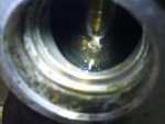
The second issue is the differential is not pinned - the spider gears "float" in the ring gear, and to pin them properly I'd have to bore a 3/8" hole in each axle shaft stub, as well as the "slip in" spider shaft that simply just lays there and is held in place by the other two spider gears on the axles. Boring into the axles in this manner was easily doable on my lathe, but crossdrilling an incredibly narrow floating spider shaft would have resulted in a a real weak part and I figured it would last exactly one romp of the throttle.

I have to rehouse the differential because the internal space of the peerless case is too close to the axles (about 1/8" - 3/16") so there is no room for flanges when I shorten the axles for an independent rear suspension. That was the original problem actually.

Combing though eBay and Craig's List I found several suitable differentials from Cub Cadet, Ariens, and other brands of smaller farm-type tractors, but all of them came with angled roller bearings and while I could use my vertical mill or the lathe to cut angled surfaces for the roller bearings to run on (these are called "cones"). It seemed like a real pain in the rear end (again, no pun intended) considering these differential assemblies were being sold without axles or axle stubs with flanges, no housing, and most of the time the sellers couldn't be bothered answering my questions regarding splines count and diameters.

I can and have cut splines on shafts before, hardened or not, but it's a lot of work, potentially without much joy in the end if I mis-index the shafts which is not that difficult to do. I just saw a lot of potential pitfalls and complexity (though, it would be fun since I enjoy using my machines) and potentially having to do it more than once to get it right.

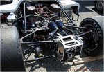
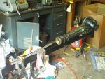
So... I saw the Audi A4 differential for $35 plus shipping and decided with all the work that's necessary to cobble some garbage together that may break early on, this complete unit while far and beyond the concept of "overkill", comes with everything I need to make the independent rear end I wanted to make in the first place:

  • A flat nose (where the torque tube originally mounted) that I can machine and weld up an adapter to hold either an electric motor or a jackshaft directly to the front of the differential housing.
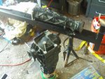
  • Instead of long axles I'd have to cut down and machine flanges for in order to build an independent rear suspension, this thing has the flanges already there. Because VW, Audi and Porsche are related in many ways from an engineering/design perspective, these axle flanges happen to precisely match the porsche 930 transmission, and I know I have two sets of brand new race-quality inner CV joints for it. I haven't dug them out of the attic yet but I know I have them. This alone made the differential very desirable.
  • It's also very narrow. Flange to flange I'd guess it's about a foot. For a vehicle that will be 4' wide, that leaves a lot of length for half-shafts, which in turn means the angles of the CV's and/or U-joints will be reasonable and not overstressed while the suspension articulates.
  • Additional "stuff". The torque tube and internal shaft came with the unit, as did the splined collar that's inside between the two. The internal shaft can be machined into a jackshaft if necessary. The mating flange of the torque tube can be easily copied to an adapter. The splined collar can be modified so it has a sprocket or pulley on it instead of a jackshaft. Or used to mate with the jackshaft. With these extra bits I have a lot of raw material to make things work in a variety of ways, and that's a good thing because sometimes the first idea doesn't work out and without extra parts of this kind I'd be back to making splined shafts and collars. Since I have the pieces, I only have to worry about half the problem in a sense.

I hope you don't mind a list, I think in lists.

But yes, a 62-lb differential assembly from a 200HP vehicle is gross overkill. But it was cheap, came with a variety of useful bits I can monkey with, and did I say it was cheap? Cheap! Even with the almost $50 it was cheap. I couldn't touch a differential of this kind locally for under $200 at any of the junkyards I visited looking for something along these lines. I originally was seeking a Toyota unit because they're much lighter, smaller, and I could take it out of the donor car with the half-shafts and CV's and cut them down and reweld them shorter to match the track of this kart. Even though welding hardened axle shafts is generally a no-no, I won't be running 100HP through them anyway so they'd survive just fine, even with my "pig welding" skills.

Anyway, that's the story about why I went with the Audi differential instead of the peerless parts. If the kart wasn't going to be 50" wide and 6' long with a wild guestimate of 800lbs dry, I would have probably pinned the peerless differential and called it a day and made a housing as I had originally planned.

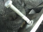
The actual trigger for all this re-engineering was my dropping the slip-in spider shaft on the floor and DENTING it. A half-inch diameter, 3" long shaft falling to the floor should not DENT upon impact. And not a little ding either. It mushroomed! I cleaned it up on the lathe and intended to put a simple washer on the end to make up the minor length difference, but that just seemed cheesy.
 
Status
Not open for further replies.
Top