bob58o
SuckSqueezeBangBlow
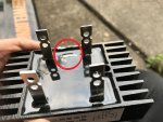
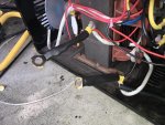
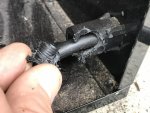
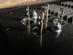
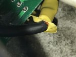
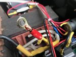
The first hurdle for me was removing the plastic screw that holds the grounding cable in place. The screw basically turned to putty the first time I tried to unscrew it. But I got it out!
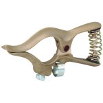
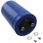
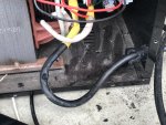
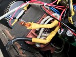
I needed some more slack. This wire will get cut and the side coming from the transformer will go to 1 of the inputs on the rectifier. The other side of this cut (connects to grounding clamp) will go to the (+) Positive side of the capacitor (when I get it). A "jumper" wire will go from the (+) Positive output of the rectifier to the (+) terminal of the capacitor. So the grounding cable will be 5-6" shorter when I'm done with it.
I needed some more slack. This wire will get cut and the side coming from the transformer will go to 1 of the inputs on the rectifier. The other side of this cut (connects to grounding clamp) will go to the (+) Positive side of the capacitor (when I get it). A "jumper" wire will go from the (+) Positive output of the rectifier to the (+) terminal of the capacitor. So the grounding cable will be 5-6" shorter when I'm done with it.
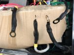
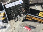
Attachments
-
 IMG_1344.jpg301.4 KB · Views: 4
 -
 IMG_1347.jpg474.5 KB · Views: 4
 -
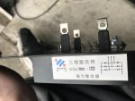
 IMG_1346.jpg369.1 KB · Views: 10

")