2015 - Learning Experience

Status
Not open for further replies.
Messages
147
Reaction score
0
Location
Kansas City, Kansas
SUCCESS!

:wai::wai::wai::wai::wai:


I was able to weld a 3rd cross beam and mount the a arms correctly giving me a 90 degree angle so the tires will run level with the ground!

I'm so relieved this worked out!

In the pic I show the finished right a arm, then the right without the a arm attached, and finally the left which shows the two cross beams I was originally going to use for mounting the a arm brackets.

Yes I know some of my welds are fat and dirty, but remember this is my first welding project!
I have a small test frame 2ft x 2ft that I beat the CRAP out of to make sure my welds were strong.
 

Attachments

  • IMG_20150514_164704[1].jpg
    IMG_20150514_164704[1].jpg
    106.4 KB · Views: 30
  • IMG_20150514_164623[1].jpg
    IMG_20150514_164623[1].jpg
    132 KB · Views: 29
  • IMG_20150514_164631[1].jpg
    IMG_20150514_164631[1].jpg
    142 KB · Views: 30
  • IMG_20150514_200136.jpg
    IMG_20150514_200136.jpg
    107 KB · Views: 31
Messages
147
Reaction score
0
Location
Kansas City, Kansas
Congrats!
Where did you get those pivots for the A-arms to attach to the spindle?!

The A-arms I got with the ball joints welded / riveted in place. I made a small bracket that I'm going to weld the spindle to, then use lock nuts to attach it to the A-arm ball joints.
 

Attachments

  • IMG_20150515_131948[1].jpg
    IMG_20150515_131948[1].jpg
    90.1 KB · Views: 10

alexV

New member
Messages
89
Reaction score
0
Location
Romania
The A-arms I got with the ball joints welded / riveted in place. I made a small bracket that I'm going to weld the spindle to, then use lock nuts to attach it to the A-arm ball joints.

I believe the pivots are tapered. They're made for a thick spindle, which is required since no kingpin is used. I know this because I have the spindle :) I'll upload a pic to show you, this weekend.

The matching spindle is also tapered, 14mm top, 12mm bottom of each hole. I think these joints take a heavy load. Just curious how your design turns out.:thumbsup:
 
Messages
147
Reaction score
0
Location
Kansas City, Kansas
I believe the pivots are tapered. They're made for a thick spindle, which is required since no kingpin is used. I know this because I have the spindle :) I'll upload a pic to show you, this weekend.

The matching spindle is also tapered, 14mm top, 12mm bottom of each hole. I think these joints take a heavy load. Just curious how your design turns out.:thumbsup:

yeah I would have just used the spindles that come with it but they were 80 bucks a pop which is insane. luckily the bolt nut itself doesn't taper, just the non-threaded part.
 

chancer

ɔ ɥ ɐ u ɔ ǝ ɹ
Messages
9,358
Reaction score
8
Location
COMFORT, TEXAS
Flux core welds. One thing I always do is immediately take a wire wheel in my drill and get that white junk off the welds. So you can see better and especially before listening to us critics here. Give us and yourself a good look at the weld not the flux dust.:thumbsup: Also if you need to touch up a bad weld you don't want to weld over that crap.:cheers2:
 
Messages
147
Reaction score
0
Location
Kansas City, Kansas
Flux core welds. One thing I always do is immediately take a wire wheel in my drill and get that white junk off the welds. So you can see better and especially before listening to us critics here. Give us and yourself a good look at the weld not the flux dust.:thumbsup: Also if you need to touch up a bad weld you don't want to weld over that crap.:cheers2:

I always take my wire brush to it if I have to take a second pass.:thumbsup:
 
Messages
147
Reaction score
0
Location
Kansas City, Kansas
picked up a seat and seat belt today got a good deal on it. fitted installed the seat belt. she has a sliding mount so should be perfect for making those adjustments for shorter or taller friends. this is just a quick mockup and yes the frame is upside down.
 

Attachments

  • IMG_20150516_133257.jpg
    IMG_20150516_133257.jpg
    110.6 KB · Views: 14
  • IMG_20150516_133343.jpg
    IMG_20150516_133343.jpg
    96.5 KB · Views: 15

alexV

New member
Messages
89
Reaction score
0
Location
Romania
Here's the spindle pictures I promised. I got them second-hand of a quad, roughly 50 US $ for spindles, hubs and drum brakes with all the nuts and washers included.

Yes, the thread part of the joint is not tapered, only the smooth part is.
 

Attachments

  • jurMIs4.jpg
    jurMIs4.jpg
    71.9 KB · Views: 9
  • UO767G7.jpg
    UO767G7.jpg
    78.3 KB · Views: 12
  • sjfrlSG.jpg
    sjfrlSG.jpg
    84 KB · Views: 15
Messages
147
Reaction score
0
Location
Kansas City, Kansas
Here's the spindle pictures I promised. I got them second-hand of a quad, roughly 50 US $ for spindles, hubs and drum brakes with all the nuts and washers included.

Yes, the thread part of the joint is not tapered, only the smooth part is.

Wow those are completely different from the ones that come with these a arms, I wish I could have gotten those.

As a side note my re-order correct size spindles came today, once I'm off work I'll get the welded up and have a rolling kart!
 
Messages
147
Reaction score
0
Location
Kansas City, Kansas
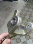
New correct length spindles arrived late last night finally got the wheel situation figured out. I had to abandon the double sided bracket idea due to the multiple pivot points. it would have been able to turn both on the a-arms and on the spindle so I got tabs welded and will be using the a arms as my pivot point.

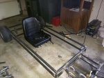
About to start welding the shock supports and mounting the shocks.

Hopefully I will also have time to add strut supports for under the seats and get the floor panel welded in place so the seat can be mounted.

I still have a ways to go but the end is in sight excluding the bodywork fenders, side panels, etc. all I have left is to hook up the steering, throttle and brake pedals, plus the roll cage.

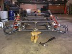
UPDATE:Got the floor panel finished as well as the shock mount and cross brace. unfortunately I ran out of flux wire before I could finish.:oops:

I'll have to pick up more in the morning and finish welding the floor pan and actually bolt the seat in.

UPDATE 2:. finish loading up the floor pan and got the seat mounted properly looks like all I have left to do is hook up the steering, gas, and break then I will be good to test drive!
 

Attachments

  • IMG_20150519_175350.jpg
    IMG_20150519_175350.jpg
    102.8 KB · Views: 20
  • IMG_20150519_175401.jpg
    IMG_20150519_175401.jpg
    143.4 KB · Views: 20
  • IMG_20150519_175305.jpg
    IMG_20150519_175305.jpg
    114.3 KB · Views: 27
  • IMG_20150519_175317.jpg
    IMG_20150519_175317.jpg
    93.7 KB · Views: 18
  • IMG_20150519_220642.jpg
    IMG_20150519_220642.jpg
    90.8 KB · Views: 19
  • IMG_20150519_220653.jpg
    IMG_20150519_220653.jpg
    92.9 KB · Views: 26
Last edited:

crazykart

Crazy member
Messages
1,167
Reaction score
1
Location
Swartz Creek, Michigan
Its looking good. As far as the welding goes you could always do like I do: weld, clean, grind near flat, reweld and repeat again lol. Last weld I just leave, no need to grind again, and I can guarantee thise parts will never come apart.
 

alexV

New member
Messages
89
Reaction score
0
Location
Romania
Those spindles start to look more heavy duty now. Did you weld mild steel to the spindle's hard steel without any problem?
 
Status
Not open for further replies.
Top