"SchizoBallz" kart build started......

madprofessor

"Loose Cannon Creations"
Messages
2,899
Reaction score
888
Location
Jacksonville, Florida
Not in any competitions.....

Don't even know how those build-off things work, RobertD. Wouldn't be in my best interests to have any guidelines or timelines anyway. This Schizoballz build is the followup to the insane DragginBallz minibike build I spent a year on previously.
That one was supposed to be so stupidly dangerous you'd need a death wish to ride it, and it exceeded at that. This build is to be likewise unique, just not in a dangerous way, so by design it would be way out of the guidelines for any group activity or comparison.
In the same way that DragginBallz could have its self-steering wheelie bar setup changed all the way from shop service thru draggin' to boonie-crashing without any tools, just wingnuts and lockwashers, Schizoballz will likewise require no tools to go schizo and change from a boonie-crasher to a flat-track racer.
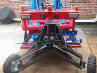
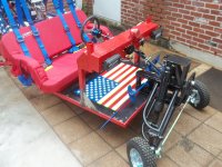
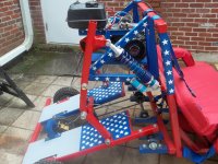
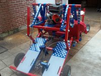
That transformer capability, the cantilevered rear suspension, the piano hinge front end, the 2/1 safety harnesses/harness, the left/center drive with telescoping wheel, all make this one another pure design/build that really wouldn't have a proper place alongside anything else.
 

madprofessor

"Loose Cannon Creations"
Messages
2,899
Reaction score
888
Location
Jacksonville, Florida
Okay, hadn't been thinking about it, but reckon it should be kept alive. I'll commit to regular posts of a hopefully informative nature, sharing some of what I've been learning, so it can be useful to others.
Most recent change I'm looking at making is in the steering. The dashboard arch that serves as what's just a steering hoop on a basic kart was designed in height and forward location before considering steering shaft angle.
End result as of today is that the angle from the arch to the nose is pretty extreme from the left-drive position. Seriously believing now that on the upcoming full test drive in a couple of days it'll be decided that the steering shaft needs to stay in the center-drive position from dash to nose. Only the wheel and shaft thru the arch would change positions in that scenario. Here's the idea.............
Already had to do away with the telescoping wheel idea to get proper strength in the setup. That frees me up to lengthen the protrusion of the shaft past the arch for better connection to the next portion. It would also allow enough protrusion to mount a sprocket to the protruding part, with a matching sprocket on the left-drive side. See what that provides?
A chain drive from center to left should make for even and smooth motion of the steering equally from either steering position. Just another step of engineering that's being the new problem of the day, as opposed to the stuff that was anticipated and/or planned for in advance.
Will post regularly from now on, with hopefully a different topic each time, try to keep this informative or at least creative. Lots of history to bandy around that I should have been posting about as it went.
 

madprofessor

"Loose Cannon Creations"
Messages
2,899
Reaction score
888
Location
Jacksonville, Florida
Here's something I've never addressed in other posts, as nobody talks about it...................
Double fuel filtering. Gravity feed from a tank to a carb should only have a single inline filter added to it to catch trash coming out of the tank, , but what about when adding a fuel pump to feed a thirsty .036 racing jet?
This kart got its factory fuel tank relocated when a top plate master kit was installed. Built mounting brackets (with soft rubber grommets) down low for clearance issues, but wanted to make it high enough for the outlet to still be above the carb inlet. That's due to the unknown of never having experienced how much you'd have to yank on the pullrope to get a pulse type (not a mechanical) pump to draw fuel up a line and start pumping it. Gravity keeps it from draining back to the tank.
Clear enough, you put a filter in that line as just described. With both the carb and also the fuel pump hence protected, why put a second filter inline between the pump and the carb? Only one good reason I can think of.................
My 90 degree plastic cone-shaped filter came with my top plate kit, and it's TRANSPARENT! You can physically see at a glance if there's fuel getting to it, and through it. Motors only need the trinity, an ignition source, oxygen, and fuel. Seeing at a glance if there's fuel not only reaching the fuel pump, but also if that's getting pumped to the carb, verifies the fuel portion of the trinity instantly. I wanted that for my motor.
Ebay sells that same transparent filter for $5, or two of them for $7. Of course I now have two mounted inline, and a spare to boot. Don't need the second one for filtering, just want it as a sightglass.
 

Budget GoKart

Aka a kenbar
Messages
2,195
Reaction score
118
Location
roachdale, indiana
i have considered making a fuel gauge by doing that but have nothing but my mtd to do that on.but my craftsman has that same type filter and thats my gauge i guess
 

madprofessor

"Loose Cannon Creations"
Messages
2,899
Reaction score
888
Location
Jacksonville, Florida
If you want something that's transparent so you can see fuel in it, I'd suggest some thickwall clear vinyl tubing from Home Depot.
I got me some in 1/4" I.D. for fuel line use and found it too stiff (thickwall) for fitting easily over pump fittings, filter fittings, etc.
Example: A section of fairly horizontal fuel line angling away from the tank. It gets cut, and a 1/4" barb tee gets spliced in with its branch pointing upward. A few inches as needed of clear tubing slips onto the barb branch, sticking up as high as the top of the fuel tank, with a plug in its end.
Voila! A liquid level sightglass.
 

madprofessor

"Loose Cannon Creations"
Messages
2,899
Reaction score
888
Location
Jacksonville, Florida
About that steering modification posted a couple of days ago................
Attaching a front view pic showing the steering shaft going through the center tube in the dash arch. To the left side of the kart (right side in the pic) you can see the hole where the shaft comes through in left-drive position. (Bottom of arch, between horn and headlight.)
Imagine a matching pair of sprockets, like maybe 12-tooths, at the two shaft tubes with a chain around them to operate together. Now imagine one side or the other gets a larger sprocket than the other, say maybe a 15-tooth.
One side would use more degrees of steering wheel revolution lock-to-lock than the other, less twitchy, less effort.
Thoughts about that?
 

Attachments

  • 100_0168.JPG
    100_0168.JPG
    2.6 MB · Views: 6

Budget GoKart

Aka a kenbar
Messages
2,195
Reaction score
118
Location
roachdale, indiana
i see alot of things on that front end and thing in general you couldve done much better you could have made way simpler steering the way you made it isnt very tough looking you couldve used a steering rack instead of performance parts and a cage would be very recommended on that thing im talking full cage and also its big enough to be registered as a golf kart
 

madprofessor

"Loose Cannon Creations"
Messages
2,899
Reaction score
888
Location
Jacksonville, Florida
Budget, the steering WAS simpler, still laughing at myself about it. Got it built the way I wanted with a sprocket moving the flat chain below it, and it was moving BACKWARDS! Decided just for fun to see if it could be added on to and still work. As to the way it started, picture the flat chain welded down BENEATH the sprocket, with no framing of any kind above that, sprocket appearing to just be "floating" above it.
Store-bought rack and pinion works fine for everyone else, but it would be a big sore thumb on this completely custom bumper-to-bumper hand-built machine. To quote Devil Anse Hatfield, "I ain't havin' it !!!"
Cut the chain section out, added some frame pieces, flipped it over, welded it on top of the sprocket. It actually works, will keep it that way for now until testing proves it to be unwieldy, hopefully not. Meanwhile, Rube Goldberg is grinning in his grave.
You're right, in that pic it isn't very tough looking. Should see it now, built like a truck. Speaking of, have I mentioned the steering shaft and u-joints are actually a brand new intermediary steering shaft for a Ford F-150 pickup? Will post a new pic this coming week, 3/8" tierods gone, replaced by 5/8" allthread sleeved into 1/2" EMT conduit, with a 5/8" allthread coupling in the middle of each for adjustments. Standoffs on the spindles gone too.
I'm neither suicidal nor stupid. Always planned it to have a rollcage, but as a removable one in three pieces for easy transport. Adding a pic to show where its legs will attach with big latch keys. 1' EMT conduit, with some 3/4" EMT sleeved inside it everywhere practical, maybe even some 1/2" too, with the legs' ends set inside of the 11 gauge 1.5" square tube.
Look at the top corners of the dashboard arch, there's a short section of 1.5" sticking up on each, and they're about 6" deep. The front legs.
Look at the backrest of the seat where the racing harnesses go over it. A section of 1.5" will be welded on the back at each corner. The back legs.
Further tough building: You can't tell all of it from any pic, but those A-arms are bad to the bone. They're 3/4" EMT on the outside where straight, and the curves are factory 3/4" sweep ells, right from the electrical aisle in H.D. They're sleeved inside all of the straight sections with 1/2" EMT, and that's 3/4" angle iron you see on the outside completely sistering up all the straight sections.
That's 3/4" x 2.25" allthread couplings and nuts welded on the ends, with 3/4" allthread acting as bolts, literally screwing in/out as they move. The BMI spindles on the ends are now tripled up in strength with steel reinforcing welded on.
Currently trying to get a junkyard title with a piece of vehicle that has the VIN on it, weld the piece to the kart frame somewhere, and order a legal Florida vanity tag, pull up next to the police, grinning like a mule eating briars! Have a pair of German stahlhelms with desert goggles for safety of course, but in Florida technically helmets won't even be legally required.
Hope that addresses all the comments, current pics to follow this week.
 

Attachments

  • 100_0164.JPG
    100_0164.JPG
    2.6 MB · Views: 3
  • 100_0172.JPG
    100_0172.JPG
    2.6 MB · Views: 3

madprofessor

"Loose Cannon Creations"
Messages
2,899
Reaction score
888
Location
Jacksonville, Florida
Full test drive done. Results as follows: It sucked eggs. Ostrich eggs. Dinosaur eggs. Built it, drove it broke it.
Whipped out the angle grinder and a fresh cutoff wheel, cut the entire front part of the steering setup off. Left only the end of the 3/4" allthread sticking out. Going to devise something else without the unnecessary resistance.
Brakes gave out almost immediately. Found I'd broken a weld on one of the tubes the dual pedals pivot in, and folded the metal plate that held the two together. Got the assembly onto the bench, reinforced it with bunches of metal and welds. The two are one, this time for real.
Primary chain was jumping on the sprocket still, snatched a half link apart. Fixed chain, found that motor mounting plate is nice and rigid on the right with a piece of 3/4" angle iron on its side, but.................
Left side that doesn't have any angle due to TC clearance issues flexes down under load, slacking off the chain tension. Will remove the motor and weld a piece of flat bar on left side that won't interfere with things, cure the skipping problem. Want to floor it so bad!
Did get the cable finished to operate the exhaust cutout. Pulls open very easily, snaps shut strong. God it's loud! That thing can call the police from 3 blocks away.
 

madprofessor

"Loose Cannon Creations"
Messages
2,899
Reaction score
888
Location
Jacksonville, Florida
Considering making the new steering setup in the front a chain drive setup.
From a sprocket on the 3/4" allthread down to a sprocket at the appropriate alignment with the A-arms to function as a pitman arm setup.
Would never have the twitchy action and short steering lock-to-lock of a straight pitman arm setup by itself. With the sprockets I can have a small one on the allthread, and a large one for the pitman arm.
The right combo of sprockets will give me the 320 degrees or so of steering wheel motion that I want. No twitch, "power steering".
 

madprofessor

"Loose Cannon Creations"
Messages
2,899
Reaction score
888
Location
Jacksonville, Florida
Backwards pitman arm setup slapped together for some testing. Could then see how to make the chain drive and pitman setup.
Ordered a 13-tooth sprocket for the steering allthread, and a 36-tooth for the pitman arm. Won't be 320 degrees of steering, but should get over 180, maybe 220 if lucky.
About a 10 day wait for parts. Will just work on a new steering shaft from wheel to dashboard tubes, welding stiffeners, aligning tierods, etc. until then.
 

madprofessor

"Loose Cannon Creations"
Messages
2,899
Reaction score
888
Location
Jacksonville, Florida
Time again to add something to this thread...................
Now that the 4.10/3.50x6 tires and rims are being stripped off for the next build, and have acquired 8" rims without hubs (4 on 4 bolt circles) with 8" wide turf tires on them, been trying to figure out how to make them fit on existing setup.
Pic shows how close the old ones sit to the frame.........
There simply isn't any kind of hub available with that kind of offset. Figured out how to extend the stud bolts with 1/2'-20 x 1.75" threaded rod couplings (16 of them, $72 w/shipping), cut a section of pipe as a spacer between hub and wheel center, blah, blah. Screw it all, forest for the trees and all that.........
Stepped back from the trees, decided to address the REAL BASE problem, cure the CAUSE not the SYMPTOM. The base problem is that the axles aren't long enough, don't stick out far enough. Live axle and the 4.5" spindles axles. Going to fix the live axle..............
Going to unscrew the 2 floorpans (now fully flag painted) on the swingarm to expose the live axle underneath. Nothing there but bare axle. Going to cut it in two on both sides, slide the ends further out.
Common 1" iron water pipe slides real neatly over 1" axles, using it for spacers in some places. Will slide it over both axle sections and weld it up, axle becomes longer, cause cured, and no more symptom. Ordering all hubs on payday.
Yippee kii yay motor mucker....................
 

Attachments

  • 100_0171.JPG
    100_0171.JPG
    2.5 MB · Views: 3

madprofessor

"Loose Cannon Creations"
Messages
2,899
Reaction score
888
Location
Jacksonville, Florida
Front hubs ordered from GPS, rear hubs and front bearings ordered from BMI. Going to start by putting the wide 8" turf tires on rear, and the skinny 8" tires on the front (have full sets of 4 of each).
Got the first one of what I'll call a successful test run yesterday on the existing little 6" skinny tires. Successful meaning it steered well enough, accelerated well for the amount of throttle put to it, and it took a couple of minutes before the primary chain stretched out and started coming off under load.
Chain jump only partly from chain stretch, it's still mainly due to the flexing downward of the 17" long flat engine mounting plate that began with just a piece of 1/2" angle iron welded along its right side. Got a piece of 1/2" flat bar welded in spots all along the left side now, and that helped immensely, just not enough.
Cut a piece of 1.5" angle iron to fit loosely between motor rack side pieces, and welded tabs to those side pieces as "shelves" for the angle to slip onto, will put ring clamp around each end and its tab to keep in place but have easy removal of angle. Angle wedges onto them tightly since it's up against the 2 pieces of 1/2" angle along the plate sides. Reduces potential flex length from 17" to 11", best I can do due to the obstructions of the sliding chain adjuster, its threaded rod, the motor mounting bolts, and the TC back plate's bearing and bosses.
Brakes don't work, even after welding up the stuff I broke. Pretty sure it's air in the system, but the super el cheapo chinese master cylinder is just too hard to work with to bleed it out. Ordered a new el cheapo so it'll bolt right up to my mounts, but this one has a reservoir cup on a hose, current one doesn't.
Confident the next test run will be a blast!
 

madprofessor

"Loose Cannon Creations"
Messages
2,899
Reaction score
888
Location
Jacksonville, Florida
Successes and fails..........Skinny 8" tires and rims successfully put on front, master cylinder replaced, just need help to bleed the air out.
Wide 8" turf tires and rims mounted with only about 2 threads on axle nuts. Chucked them, put on skinny set that matches front. Still had to cut the rear bumper ends off, even for the skinny tires. Too bad, was going to attach fenders there.
Frame clearance rose from 12" to 15.5" though, nice bonus. Will still be able to scrape the ground when transformed to flat track mode, Monroe air shocks and reverse mounted swingarm bearings make that happen.
Scratch the cutting of axle on both ends to make it longer, not seeing the forest for the trees again. Only going to cut it on ONE side, slide BOTH the long section and short section about 1.25", making about 2.5" gap on one side only. Sleeve the one gap with 1" iron pipe and weld with multiple passes. Plenty of 1" axle and .75" stepped down threads sticking out on both sides as was planned for two cuts.
Note: Because the two planned sleeves would have prevented ever getting sprocket hub, brake disc, and two inside bearings off, was about to spend $74 instead for a 54" axle from MFG. Now will be free again, and all parts removeable.
 

madprofessor

"Loose Cannon Creations"
Messages
2,899
Reaction score
888
Location
Jacksonville, Florida
Learning about hydraulic brakes the hard way, spent hours trying to make the caliper stop that 1" solid axle. Blamed everything for it, then found out the 8" solid brake disc wasn't even tight to the axle. Had never even put a piece of 1/4" keystock in it, much less tightened the set screws.
Fixed that, still wouldn't stop it, knew that somehow things weren't bleeding off correctly.
I'm a highly experienced and great scuba diver, don't air bubbles rise? Not in the tiny passage of a 84" brake line they don't. Got it bled with end laying on floor, finally have brakes. Learning curves, huh?
Cutting and rewelding for chain tension on front end's chain drive steering, tripled up strength of pitman arm, all in primer. Rest time.
 
Top