Reusing modules out of Nissan Leaf Battery Packs

Functional Artist

Well-known member
Messages
4,410
Reaction score
1,692
Location
Toledo, Ohio
I have been researching the re-use of individual "Leaf" (Lithium battery) modules :idea2:
...ones that have been, removed from Nissan Leaf (cars) vehicles

Here is some info on them (it's kinda long but, if interested, it has lots of good info)
https://www.youtube.com/watch?v=vYQJatWpBXY&t=20s


I currently have a 48V 45AH pack, out of a Chevy Volt, on my El Moto
http://www.diygokarts.com/vb/showthread.php?t=37062

But, being that my "Volt" battery pack is only 12S (45V nominal), the top charge voltage is only ~49.8V

So currently, my top speed is only ~35MPH
...but, I must say, that it get's there really, really quick :2guns:
…plus, with it's 45AH capacity, my range is only ~25 miles :huh:

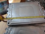
So, it looks like, if I move up to/use (7) of these 7.5V Leaf modules, which would "actually" be 14S (52.5V nominal)
...it would have a top charge voltage of ~54V (which should increase my top speed a bit)
...& with it's 66AH capacity (my range should increase a bit too) :cheers2:


Maybe something like this (~$475.00)
https://www.ebay.com/itm/Solar-RV-Ni...1&isGTR=1#shId

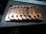
It's (7) individual Leaf cells
…including a BMS
...plus a printed circuit board (for connecting the BMS)

* But, while researching, I've come across some negative (-) info about these cells (like loosing capacity)
https://www.mynissanleaf.com/viewtopic.php?f=27&t=26662

This is very concerning, when contemplating buying these type of cells
...especially, pre-used ones

So, I am interested in any opinion &/or info on re-using these Leaf cells
…& also, this printed circuit board, BMS connection concept (in eBay ad)
 

Attachments

  • Leaf batt plus BMS board.png
    Leaf batt plus BMS board.png
    8.7 KB · Views: 142
  • leaf BMS.jpg
    leaf BMS.jpg
    1.5 KB · Views: 141
  • BMS board.jpg
    BMS board.jpg
    1.4 KB · Views: 140

Kartorbust

Well-known member
Messages
3,901
Reaction score
194
Location
Utica, NE
I'd have to look through the build, but for quick references, what are the dimensions of these and estimation on the weight? It's a cool idea to reuse them, long as you get ahold of a set that's not completely burned out...most get reused for battery backup for street lights.
 

anickode

Active member
Messages
2,296
Reaction score
14
Location
S.E. Michigan
I think the big issue with the Leaf batteries losing capacity was heat. They weren't really intended to be used and charged in the 120°+ temps in the desert Southwest, so that's where most of the failures occurred.
 

Functional Artist

Well-known member
Messages
4,410
Reaction score
1,692
Location
Toledo, Ohio
I think the big issue with the Leaf batteries losing capacity was heat. They weren't really intended to be used and charged in the 120°+ temps in the desert Southwest, so that's where most of the failures occurred.

Yup, :iagree:

Also, I read that there were some BMS or software issues :huh:
...that kinda killed, from what I understand to be, otherwise perfectly good modules

But, if buying these cells used & "loose" (removed from a whole pack)
...is there a test or way to know there "good" or not damaged?

The voltage can be easily tested :thumbsup:
...but, the capacity?
...or ?
 

anickode

Active member
Messages
2,296
Reaction score
14
Location
S.E. Michigan
Yup, :iagree:

Also, I read that there were some BMS or software issues :huh:
...that kinda killed, from what I understand to be, otherwise perfectly good modules

But, if buying these cells used & "loose" (removed from a whole pack)
...is there a test or way to know there "good" or not damaged?

The voltage can be easily tested :thumbsup:
...but, the capacity?
...or ?

If they list the model year they came from it would be helpful. They made some changes and did a software patch on the charging system for the later models I believe.

---------- Post added at 07:29 PM ---------- Previous post was at 07:27 PM ----------

hey man I would use these batteries https://www.youtube.com/watch?v=2tTV3lBMs9g&t=285s but you would need a lot of them and need to solder them together. But hey it's worth a shot.

---------- Post added at 04:58 PM ---------- Previous post was at 04:47 PM ----------

but I advise not to charge fast or over charge. they can explode.

They can also explode from soldering them together. Soldering is slow and the heat has time to soak in. You've gotta be running a real hot iron so you can do it quick.

Spot weld and nickel strip is a much better way to go.
 

Bgt2u

Member
Messages
116
Reaction score
2
Location
Originally: Nantucket, Ma (currently living in Sil
I have also been considering the Leaf modules for my little ride, and l have the same conerns about their actual useable capacity, and lifespan. One question comes to mind...for me at least, What do you use for a charger?
 

Attachments

  • Studio_20200127_213407.jpg
    Studio_20200127_213407.jpg
    433.8 KB · Views: 6

Functional Artist

Well-known member
Messages
4,410
Reaction score
1,692
Location
Toledo, Ohio
I have also been considering the Leaf modules for my little ride, and l have the same conerns about their actual useable capacity, and lifespan. One question comes to mind...for me at least, What do you use for a charger?

Nice ride :thumbsup:

I've been doin' some researchin' on that question :2guns:

These type lithium cells cannot be over-charged past 4.15V per cell
…but, only charging to ~4.0V per cell would give a bit of a "safety" margin :cheers2:

So, IMO for a 7 module set (basically 14 cells in series or 14S) out of a Nissan Leaf, like described above, the proper lithium charger should have a top charge cut-off of ~57V (4.07V x 14 = 56.98V)

BUT, be aware that this 57V "top charge voltage" could be "too high" of a voltage for a standard 48V system (like yours)

From what I understand, most of these small electric motor/controllers are set up/designed for use with Lead batteries
…& as such, a 48V system would usually never see (or have to deal with) anything over ~54V "tops"
(4-12 SLA's fully charged @ ~13,3V = 53.2V (13.3V x 4 = 53.2V)

It may be able to handle it
...but, who knows :huh:

Just wanted to kinda answer your question :cool:
 

Functional Artist

Well-known member
Messages
4,410
Reaction score
1,692
Location
Toledo, Ohio
I'd have to look through the build, but for quick references, what are the dimensions of these and estimation on the weight? It's a cool idea to reuse them, long as you get ahold of a set that's not completely burned out...most get reused for battery backup for street lights.

These modules seem to be ~12" x 9" x 1 1/2" thick
…& weigh a little over 8 lbs. each

So, a stack of (7) modules would be ~ 12" x 9" x 10 1/2"
…& weigh ~57 lbs. :thumbsup:

Here are a some (a set of 8) for ~$470.00 (~$60.00 per module)
https://www.ebay.com/itm/Nissan-Lea...a=1&pg=2334524&_trksid=p2334524.c100667.m2042

The ad says,
"Nissan Leaf Battery Module G2 Lot of 8 2014 7.6V TESTED!!"
"43AH. Tested all modules at 43Ah. Tested from 8.3v to 5v at 20 amps."

Cell Voltage
Maximum: 4.15V
Nominal: 3.8V
Minimum: 2.5V

Module Voltage
Maximum: 8.3V
Nominal: 7.6V
Minimum: 5V

So, these seem to be the newer G2 (second generation) modules. :2guns:
 

Bgt2u

Member
Messages
116
Reaction score
2
Location
Originally: Nantucket, Ma (currently living in Sil
Thank you, for the compliment on my "little ride". It's funny, l already am one of the watchers on that eBay listing, so, l guess l am headed in the right direction. As far as the 57v top cut off, l know that people have "overvolted" these particular motors (that l am using) and not had any immediate problems. Over time, hoever, l am sure that it would take an adverse toll on them, so, l would just proceed with caution. For now, ln the meantime, l am temporarily going to parallel four 13s3p (48v-10.5ah) ebike battery packs (totalling 54.6v), and hope for the best. They each have their own BMS, so l will have to charge them individually. One question l still have for the Leaf modules, is: where do l obtian a charger for them? I have heard many stories about them swelling do yo improper charging. Do you have any suggestions, or maybe you could point me in the right direction as far as finding one?
 

Functional Artist

Well-known member
Messages
4,410
Reaction score
1,692
Location
Toledo, Ohio
Thank you, for the compliment on my "little ride". It's funny, l already am one of the watchers on that eBay listing, so, l guess l am headed in the right direction. As far as the 57v top cut off, l know that people have "overvolted" these particular motors (that l am using) and not had any immediate problems. Over time, hoever, l am sure that it would take an adverse toll on them, so, l would just proceed with caution. For now, ln the meantime, l am temporarily going to parallel four 13s3p (48v-10.5ah) ebike battery packs (totalling 54.6v), and hope for the best. They each have their own BMS, so l will have to charge them individually. One question l still have for the Leaf modules, is: where do l obtian a charger for them? I have heard many stories about them swelling do yo improper charging. Do you have any suggestions, or maybe you could point me in the right direction as far as finding one?

I've been thinking on this a bit more :thumbsup:

Keep in mind, over dis-charging lithium cells is what "kills" them
...& over-charging them is what causes the swelling (& in worst case scenario's bursting & outgasing) :ack2:

So, for "safely" DIY charging, a DIY pack of used modules like these, it's usually recommended to only charge them up to ~4.15V (max) per cell
…or for these Leaf modules 8.3V (max) per module

But, I've noticed that most Lithium battery chargers are set to charge these type Lithium cells to 4.20V.
Which may be OK or proper on new cells but, IMO very dangerous on a pack of used cells.

As I said, in my opening post, it looks like (7) of these modules (14S) would give me the most "boost" in my (48V) situation. :wai:

But, most chargers for 14S lithium battery packs have a 58.8V top charge setting
(charging them up to 4.2V per cell)
...but, that leaves NO "safety margin" what so ever.

* I know this is where a BMS usually comes into play
...but, I'm trying to set it up "simple"

** Set it up right in the beginning, monitor the voltages & only balance when & if necessary (like I've been doing with my Chevy Volt pack)

Here is a video of my Digital Battery Balance Monitor
https://www.youtube.com/watch?v=uzwUiSl0Azg

So, I was thinking, maybe a standard, off the shelf, charger for a 13S Lithium pack, with it's 4.2V top charge, would only charge a 14S pack up to 54.6V (3.9V per cell)
...like this one, 48V 15A (~$100.00)
https://www.ebay.com/itm/YZPOWER-54-...g/283423911361

It looks like using a (13S) charger would give a .3V "safety margin" per cell
…& a 4.2V "safety margin" for the entire (14S) pack

This should also help to NOT "over-voltage-stress" my 48V components like the main contactor &/or DC to DC voltage convertor.

I know these 48 components can handle ~54V (because the top charge voltage for a standard 48V Lead battery pack = ~53.2V)
...but, I'm not sure if they would be able to handle almost 59V
 

Functional Artist

Well-known member
Messages
4,410
Reaction score
1,692
Location
Toledo, Ohio
Steppin' my game "up a notch"

I went ahead & bought (7) of the Lithium battery modules, out of a 2014 Nissan Leaf electric car from GreenTecAuto :thumbsup:
https://www.ebay.com/itm/Nissan-Leaf-...

They were ~$60.00 ea. ($60.00 x 7 = $420.00)
...but, there was a 10% off code available ($420.00/10% = $42.00) ($420.00 - $42.00 = $378.00)
So, after tax, I picked 'em up for ~$400.00 :cheers2:

Now, for some specific specifications on these specific type of Lithium battery cells :cornut:

The chemistry of these cells: Lithium Ion LiMn2O4/LiNiO2
The country/Region of Manufacture: Japan

VOLTAGE SPECIFICATIONS

Cell Voltage
Maximum: 4.15V
Nominal: 3.8V
Minimum: 2.5V

Module Voltage
Maximum: 8.3V
Nominal: 7.6V
Minimum: 5V

MODULE SPECIFICATIONS
Number of cells 4
Construction 2 in-series, 2 in parallel
Length 11.9291" (303 mm)
Width 8.7795" (223 mm)
Thickness 1.3779" (35 mm)
Weight 8.3775 lbs (3.8 kgs)
Output terminal M6 nut
Voltage sensing terminal M4 nut

CELL SPECIFICATIONS
Cell type Laminate type
Cathode material LiMn2O4 with LiNiO2
Anode material Graphite
Rated capacity (0.3C) 33.1 Ah
Average voltage 3.8 V
Length 11.417" (290 mm)
Width 8.504" (216 mm)
Thickness 0.2795" (7.1mm)
Weight 1.7624 lbs (799 g)

I measured the modules & got
...~1 1/4" thick
...~8 3/4" wide
…~12 1/2" long (with terminals)
…& just under 10" tall, for the whole stack of (7)

I did a quick unpacking/intro video :2guns:

https://www.youtube.com/watch?v=AfiJDzaZGZc
 

Attachments

  • SAM_2617.JPG
    SAM_2617.JPG
    309.2 KB · Views: 3
  • SAM_2616.JPG
    SAM_2616.JPG
    317.7 KB · Views: 2
  • SAM_2615.JPG
    SAM_2615.JPG
    312.5 KB · Views: 3
  • SAM_2614.JPG
    SAM_2614.JPG
    310.7 KB · Views: 3
  • SAM_2564.JPG
    SAM_2564.JPG
    307 KB · Views: 2
  • SAM_2620.JPG
    SAM_2620.JPG
    307.6 KB · Views: 2
  • SAM_2619.JPG
    SAM_2619.JPG
    312.9 KB · Views: 2
  • SAM_2618.JPG
    SAM_2618.JPG
    312.2 KB · Views: 2
  • SAM_2622.JPG
    SAM_2622.JPG
    312.1 KB · Views: 5
  • SAM_2623.JPG
    SAM_2623.JPG
    313.2 KB · Views: 2

Functional Artist

Well-known member
Messages
4,410
Reaction score
1,692
Location
Toledo, Ohio
Cooling Fins

I've been doin' some thinkin' about using these modules :idea2:
How to connect 'em together (both physically & electrically)
...contemplating different mounting possibilities
…monitoring the "internals"
...& even potential cooling ideas :thumbsup:

First thing to keep in mind when working with these "pouch" type modules is that ya gotta keep 'em "clamped" together, with some light, even pressure, on both sides, which helps 'em maintain their shape :cheers2:

Usually, a metal plate is used, on each end, to maintain the pressure on them when the whole "pack" is "clamped" together, using long "thru bolts"


So I was thinkin, what if (lets say) a piece of metal (aluminum?) was "waffered" in between each of the modules, as well as on the ends
…& maybe, have 'em sticking out ~1/4" on each side

This would give the "pack" a unique look (think like cooling fins on a motorcycle engine)
...& act as "heat sinks" helping to draw any excessive heat out of the pack (if necessary) :2guns:
 

Functional Artist

Well-known member
Messages
4,410
Reaction score
1,692
Location
Toledo, Ohio
Bus Bars

We are gonna need some Bus Bars to "electrically" connect these modules together :thumbsup:

Bus Bars are basically just flat pieces of copper with some holes in 'em
(think short/solid/flat battery cables)

So, lets look into it a bit deeper :cheers2:

Here's some interesting/pertinent info: :2guns:


"Conductor Size
Calculating conductor size is very important to the electrical and mechanical properties of a bus bar. Electrical current-carrying requirements determine the minimum cross-sectional area of the conductors. Mechanical considerations include rigidity, mounting holes, connections and other subsystem elements. The table below can be used to approximately calculate the conductor size at a given steady state current with a resulting self-heating temperature rise. This table is generally used for currents above 300 amps. For currents below 300 amps, please refer to the design guide formula. You can find ampacity charts and comparative graphs at the Copper Development Association’s website, copper.org.

1/8 x 3/4
30 °C Rise Skin Effect Ratio at 70° C = 1.00 60-Hz Ampacity,* Amp = 215
50 °C Rise Skin Effect Ratio at 90° C = 1.00 60-Hz Ampacity, *Amp = 285
65 °C Rise Skin Effect Ratio at 105° C = 1.00 60-Hz Ampacity, *Amp = 325"
https://www.busbar.com/resources/copper-ampacity/


Looking at the modules & the chart (above), it looks like some 1/8" x 3/4" x (maybe) 3" pieces of copper bar should easily meet the physical & electrical requirements of connecting these modules :cool:

Here's some more ;)


"Design Guide Formulas
Conductor Size
Calculating conductor size is very important to the electrical and mechanical properties of a bus bar. Electrical current-carrying requirements determine the minimum width and thickness of the conductors. Mechanical considerations include rigidity, mounting holes, connections and other subsystem elements. The width of the conductor should be at least three times the thickness of the conductor.
Hide

Additions of tabs and mounting holes change the cross-sectional area of the conductor, creating potential hot spots on the bus bar. The maximum current for each tab or termination must be considered to avoid hot spots.

Cross-sectional area and the length determine bus bar conductor size. Cross-sectional area (..4) is equal to conductor thickness (t) multiplied by conductor width (w).

A value of approximately 400 circular mils per ampere is a traditional basis for design of single conductors. Since bus bars are not round, circular mils must be converted to mils squared (simply multiply the circular mils value by 0.785).

The following formula determines the minimum cross-sectional area of a conductor. This area should be increased by five percent for each additional conductor laminated into the bus structure. This extra five percent is a safety factor compensating for the compounding heat gain within the conductors.

This equation calculates the minimum cross-sectional area necessary for current flow:

Cross Sectional Area Conductor Flow

A = Cross-sectional area of the conductor in inches 2
l = Max DC current in amperes
N = Number of conductors in the bus assembly

To calculate the cross-sectional area of an AC current source, you must take frequency into consideration (See the section on Skin Effect).

Note: This formula has a breakdown point at approximately 300 amps of current. For calculations involving larger currents, we suggest you contact a Mersen engineer and refer to the ampacity table. In addition, you can find ampacity charts and comparative graphs at the Copper Development Association’s website, copper.org.


Capacitance
Capacitance of the bus arrangement depends upon the dielectric material and physical dimensions of the system. Capacitance varies only slightly with frequency change, depending on the stability of the dielectric constant. This variation is negligible and therefore is omitted in this analysis:

Skin effect
Because of skin effect phenomena, inductance and resistance are dependent on frequency. At high frequency, currents tend to flow only on the surface of the conductor. Therefore the depth of penetration of the electromagnetic energy determines the effective conducting volume.

Inductance
Maintaining a low inductance results in a low characteristic impedance and greater noise attenuation. When minimum inductance is a design objective, consider these tips:
1. Minimize the dielectric thickness.2. Maximize the conductor width.3. Increase the frequency.
There are two types of inductance to be determined: internal inductance, which is a result of flux linkages within a conductor, and external inductance, which is determined by the orientation of the two current carrying conductors.

Resistance
To calculate the DC conductor resistance, the following formula applies (Resistance at 20°C):

Voltage drop
As current travels across a conductor, it loses voltage. This is caused by the resistivity of the conductor. The losses are referred to as voltage drop. Use this formula to calculate the voltage drop across the conductors:

Impedance
In the design of laminated bus bars, you should consider maintaining the impedance at the lowest possible level. This will reduce the transmission of all forms of EMI (electromagnetic interference) to the load."

This info plus more on the formulas & equations can be found here:
https://www.busbar.com/resources/formulas/
 

AndyW

New member
Messages
19
Reaction score
14
We are gonna need some Bus Bars to "electrically" connect these modules together :thumbsup:

Bus Bars are basically just flat pieces of copper with some holes in 'em
(think short/solid/flat battery cables)

So, lets look into it a bit deeper :cheers2:

Here's some interesting/pertinent info: :2guns:


"Conductor Size
Calculating conductor size is very important to the electrical and mechanical properties of a bus bar. Electrical current-carrying requirements determine the minimum cross-sectional area of the conductors. Mechanical considerations include rigidity, mounting holes, connections and other subsystem elements. The table below can be used to approximately calculate the conductor size at a given steady state current with a resulting self-heating temperature rise. This table is generally used for currents above 300 amps. For currents below 300 amps, please refer to the design guide formula. You can find ampacity charts and comparative graphs at the Copper Development Association’s website, copper.org.

1/8 x 3/4
30 °C Rise Skin Effect Ratio at 70° C = 1.00 60-Hz Ampacity,* Amp = 215
50 °C Rise Skin Effect Ratio at 90° C = 1.00 60-Hz Ampacity, *Amp = 285
65 °C Rise Skin Effect Ratio at 105° C = 1.00 60-Hz Ampacity, *Amp = 325"
https://www.busbar.com/resources/copper-ampacity/


Looking at the modules & the chart (above), it looks like some 1/8" x 3/4" x (maybe) 3" pieces of copper bar should easily meet the physical & electrical requirements of connecting these modules :cool:

Here's some more ;)


"Design Guide Formulas
Conductor Size
Calculating conductor size is very important to the electrical and mechanical properties of a bus bar. Electrical current-carrying requirements determine the minimum width and thickness of the conductors. Mechanical considerations include rigidity, mounting holes, connections and other subsystem elements. The width of the conductor should be at least three times the thickness of the conductor.
Hide

Additions of tabs and mounting holes change the cross-sectional area of the conductor, creating potential hot spots on the bus bar. The maximum current for each tab or termination must be considered to avoid hot spots.

Cross-sectional area and the length determine bus bar conductor size. Cross-sectional area (..4) is equal to conductor thickness (t) multiplied by conductor width (w).

A value of approximately 400 circular mils per ampere is a traditional basis for design of single conductors. Since bus bars are not round, circular mils must be converted to mils squared (simply multiply the circular mils value by 0.785).

The following formula determines the minimum cross-sectional area of a conductor. This area should be increased by five percent for each additional conductor laminated into the bus structure. This extra five percent is a safety factor compensating for the compounding heat gain within the conductors.

This equation calculates the minimum cross-sectional area necessary for current flow:

Cross Sectional Area Conductor Flow

A = Cross-sectional area of the conductor in inches 2
l = Max DC current in amperes
N = Number of conductors in the bus assembly

To calculate the cross-sectional area of an AC current source, you must take frequency into consideration (See the section on Skin Effect).

Note: This formula has a breakdown point at approximately 300 amps of current. For calculations involving larger currents, we suggest you contact a Mersen engineer and refer to the ampacity table. In addition, you can find ampacity charts and comparative graphs at the Copper Development Association’s website, copper.org.


Capacitance
Capacitance of the bus arrangement depends upon the dielectric material and physical dimensions of the system. Capacitance varies only slightly with frequency change, depending on the stability of the dielectric constant. This variation is negligible and therefore is omitted in this analysis:

Skin effect
Because of skin effect phenomena, inductance and resistance are dependent on frequency. At high frequency, currents tend to flow only on the surface of the conductor. Therefore the depth of penetration of the electromagnetic energy determines the effective conducting volume.

Inductance
Maintaining a low inductance results in a low characteristic impedance and greater noise attenuation. When minimum inductance is a design objective, consider these tips:
1. Minimize the dielectric thickness.2. Maximize the conductor width.3. Increase the frequency.
There are two types of inductance to be determined: internal inductance, which is a result of flux linkages within a conductor, and external inductance, which is determined by the orientation of the two current carrying conductors.

Resistance
To calculate the DC conductor resistance, the following formula applies (Resistance at 20°C):

Voltage drop
As current travels across a conductor, it loses voltage. This is caused by the resistivity of the conductor. The losses are referred to as voltage drop. Use this formula to calculate the voltage drop across the conductors:

Impedance
In the design of laminated bus bars, you should consider maintaining the impedance at the lowest possible level. This will reduce the transmission of all forms of EMI (electromagnetic interference) to the load."

This info plus more on the formulas & equations can be found here:
https://www.busbar.com/resources/formulas/

Hi FA. I’m new to the forum and I’m planning an electric go cart build. I was curious if you ever installed and used these leaf battery modules. I was considering them for my project. Thanks.

Andy
 

Functional Artist

Well-known member
Messages
4,410
Reaction score
1,692
Location
Toledo, Ohio
Hi FA. I’m new to the forum and I’m planning an electric go cart build. I was curious if you ever installed and used these leaf battery modules. I was considering them for my project. Thanks.
Andy

Howdy & welcome :welcome2:

I haven't used 'em on my bike (it's been running so good, I've just been riding 'er :thumbsup:
...but actually, I've been workin' on/designing a kart around these cells :cool:

Designation: USSK Voyager ::sifone:

I ordered/got some 1/8" x 3/4" copper bars
...they should work good to connect these Leaf cells :wai:

So, I measured, marked, cut, rounded & drilled a bunch of 'em :2guns:
 

Attachments

  • SAM_6324.JPG
    SAM_6324.JPG
    315.6 KB · Views: 3
  • SAM_6323.JPG
    SAM_6323.JPG
    314.7 KB · Views: 3
  • SAM_6321.JPG
    SAM_6321.JPG
    313.5 KB · Views: 2
  • SAM_6319.JPG
    SAM_6319.JPG
    312.7 KB · Views: 2
  • SAM_6301.JPG
    SAM_6301.JPG
    309.5 KB · Views: 2
  • SAM_6328.JPG
    SAM_6328.JPG
    306.4 KB · Views: 3
  • SAM_6329.JPG
    SAM_6329.JPG
    310.8 KB · Views: 3
  • SAM_6331.JPG
    SAM_6331.JPG
    313.5 KB · Views: 3
  • SAM_6330.JPG
    SAM_6330.JPG
    315.6 KB · Views: 3

AndyW

New member
Messages
19
Reaction score
14
Howdy & welcome :welcome2:

I haven't used 'em on my bike (it's been running so good, I've just been riding 'er :thumbsup:
...but actually, I've been workin' on/designing a kart around these cells :cool:

Designation: USSK Voyager ::sifone:

I ordered/got some 1/8" x 3/4" copper bars
...they should work good to connect these Leaf cells :wai:

So, I measured, marked, cut, rounded & drilled a bunch of 'em :2guns:

Thanks. I like the homemade copper buss bars. The 2 seater off road electric kart I'm looking to do is going to be heavy so I plan on doing a 72V system with 110A max continuous current to supply a 10kW motor. I'm looking at suppling power with either a bank of 10 Leaf modules or building my on battery out of 21700 cells. There seems to be pros and cons to both battery systems.
 

Tucktuck84

New member
Messages
2
Reaction score
0
Location
Chattanooga
Try using LG Chem batteries they are 3.7v nominal and 120ah each they are pricey at about .49.99 each but they do have a continuous discharge rate of 200 ramps. If that's to much weight or size your can try the spin08hp cells at around 5 bucks each they are 3.7 nominal and 8ah with 200amp continuous discharge as well.
I've been experimenting with these and wheelchair motors with 16 in total height rim and tires. The wheelchair tires are 8ins standard I have and were rated at 6-7 mph. So my 16 inch tire upgrade will double that number. I'm using a small 1 seat gokart frame I welded up some motor stands and have 4 of these motors one on each wheel. I weighted my frame in comparison to the full weight with batteries to the karts and it's almost 120lbs lighter with the lead acid batteries. With the LG Chem batteries around 150 lighter. I salvaged 4 electric scooters twist throttles and modules for free ran 1 to each motor and hard to explain how but put two of the twist throttles on each of side of my straight bat steer wheel. It works but kinda like a zero turn which I'll have to do something else obviously. I use 7s pack and I've never gone down to half battery yet. I opted out of using a BMW system so I simply put a voltage meter and a 7s capacity level read out attached to my steering. I'm gonna try to run all 4 from 1 twist throttle but I suspect it will burn the one out fairly quickly. I've only gotten to around 12mph on it so far I'd prefer to upgrade the suspension before I try top speed and fix the throttle. Last thing I need is to try accidentally turning left at 20 plus on a dime.
 

Functional Artist

Well-known member
Messages
4,410
Reaction score
1,692
Location
Toledo, Ohio
Try using LG Chem batteries they are 3.7v nominal and 120ah each they are pricey at about .49.99 each but they do have a continuous discharge rate of 200 ramps. If that's to much weight or size your can try the spin08hp cells at around 5 bucks each they are 3.7 nominal and 8ah with 200amp continuous discharge as well.
I've been experimenting with these and wheelchair motors with 16 in total height rim and tires. The wheelchair tires are 8ins standard I have and were rated at 6-7 mph. So my 16 inch tire upgrade will double that number. I'm using a small 1 seat gokart frame I welded up some motor stands and have 4 of these motors one on each wheel. I weighted my frame in comparison to the full weight with batteries to the karts and it's almost 120lbs lighter with the lead acid batteries. With the LG Chem batteries around 150 lighter. I salvaged 4 electric scooters twist throttles and modules for free ran 1 to each motor and hard to explain how but put two of the twist throttles on each of side of my straight bat steer wheel. It works but kinda like a zero turn which I'll have to do something else obviously. I use 7s pack and I've never gone down to half battery yet. I opted out of using a BMW system so I simply put a voltage meter and a 7s capacity level read out attached to my steering. I'm gonna try to run all 4 from 1 twist throttle but I suspect it will burn the one out fairly quickly. I've only gotten to around 12mph on it so far I'd prefer to upgrade the suspension before I try top speed and fix the throttle. Last thing I need is to try accidentally turning left at 20 plus on a dime.

Can you post a link to them 120Ah LG cells (~$49.00)

Sounds like a kool project :thumbsup:

Have you seen my Zero kart?
...here is a video of when I rode it up to the ice cream shop :popcorn:
...& got pulled over by the police :smiley_omg:
https://www.youtube.com/watch?v=Rss3YOJPBFY
 

Tucktuck84

New member
Messages
2
Reaction score
0
Location
Chattanooga
Ask requested the place I source my lithium batteries and lipo4 batteries is batteryhookup.com

I dont think that they have any single cell lg Chem in stock the spin08hp 3.7 8ah at 4 bucks are cheap enough and put out 200amp as well you have a 3 12v 36v series set up I'd just buy 9 of these I have about 15 of them an run a power wheelchair around just fine. They also fit 9 easy in a plastic ammo box from harbor freight ingot for 2.99 makes a great battery enclosure.
 
Top