This is an electronics continuation / summary of the thread started by bob58o named Predator Lighting coil. It is a story as one struggles through the challenges of figuring out most of the mechanics and electrical of this topic. Pics, Charts, Graphs! Great questions and conclusions. The thread slowed and then closed.

Now in find myself, after installing an electric start kit, seeking higher current output. Before the starter kit I was using a Lighting coil, bridge (full) rectifier, 0.1F 25V capacitor and 36 watt Nilight Head LED’s with a couple of watt tail LED’s. Work great for 2 years.
The following is mostly confirmed using Honda GX200 documentation found on line. My final goal is to get a 7A charging system in by maybe fall. Still have gearing to finish and new shocks taking priority before an upgrade to the 3A charge system. Almost forgot disk brake upgrade.
From common sense, and the images below, we can deduce the following:
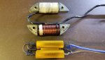
1) Charging coils are intended to charge batteries while driving 12DC loads and are available in 1A, 3A and 7A. These are ~ twice the voltage of lighting coils to leave enough voltage after rectification.
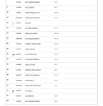
2) Lighting coils are intended to power incandescent AC bulbs on vehicles without starters. They are available in 15W and 25W with series / parallel combinations to achieve 12V “Nominal” and 15W to 50W.
3) Charge coils use the 3 magnet flywheel, Lighting coils use the 2 magnet flywheel.
Rectification and Regulation for Charging Coils:
1A and 3A coils are single wire while the other end is connected to ground. They can only be ½ waveform rectified since the coil ground is connected to battery / regulator ground. Google Bridge Rectifier Diagram for further details.
I tried one of the common 3 wire Rectifier/Regulator on my 12V 50W lighting coil and I got unusable DC voltage.
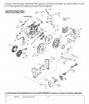
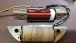
The 7A charge coil is a different animal and this is where I’m going next. If anyone out there has tried it please let us know. Looks like a stator to me, see below. 3 of the 4 posts have windings and is ungrounded, I assume, since it has 2 wires. Not many vendors carry it and the Honda OEM is expensive. Kohler has a less expensive substitute.
From NR Racing:
Honda OEM 7A Coil $210
Kohler 7A Coil $70
Honda OEM 7A Rectifier/Regulator $131
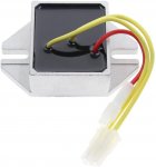
There are substitute 7A regulators on Amazon for $45-50. These are 5 wire and a harness is included with at least one. Pinout pictured below. These bring out of the case the DC- so it can be connected directly to the battery for an accurate charge voltage. Since I chose not to use the starter kit switch panel and I didn’t install any accessory switch (key on) I’ll probably try this one without the accessory pin functional:
UPDATE 8/8/20: Regulator below won't work, 3 wire AC Input
Amazon Regulator $44
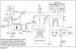
The final image is the Wiring Diagram of my Yerf Dog 3202 with P212 not using the switch panel included in the kit and 1N5408 from the key for ½ waveform rectification 3 amp output. So when I run my lights the battery doesn’t charge.
As I find anything more specific or better images from now until I install the charging upgrade I'll post here.
Attachments
-
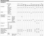 GX200 Model Number Options.png123.7 KB · Views: 75
 -
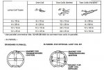 GX200 Lighting Coil Config Options.jpg59.8 KB · Views: 81
 -
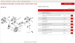 Honda GX200 QG2 7 Amp Charge Parts Diagram.png159.9 KB · Views: 70
 -
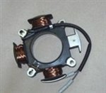 7 Amp Charge Coil.jpg15.3 KB · Views: 136
 -
 Go Cart Wiring Diagram 1.jpg97.5 KB · Views: 89