Making an electric go kart

Davidgo06

New member
Messages
20
Reaction score
1
Hi,
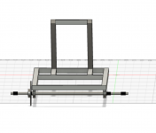
I am designing the go kart in a 3D cad, for the moment I have in mind the structure that I'm going to make and I started to desing it ( i will post some pics below ).
I just wanted to make this thread to ask some questions and to share my progress on this project :D.
Captura de pantalla 2021-09-03 a las 15.59.41.pngCaptura de pantalla 2021-09-03 a las 15.59.29.png
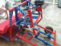
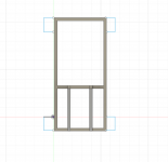
This is the structure ( it is not finished yet because I am trying to find the steering axel and the rear axel, so I can continue it)

Here is my first question, I have a problem with the structure because it is no wide enough ( 55 cm ) so I can't find any axles, so what I have in mind is to expand the sides ( I don't know how much yet ) or the other thing is to expand it only where the axle will be, I will put a pic so you can understand it better😅.Captura de pantalla 2021-09-07 a las 1.20.52.png
 

Attachments

  • 1630970040341.png
    1630970040341.png
    153.2 KB · Views: 1

Davidgo06

New member
Messages
20
Reaction score
1
Functional Artist it is incredible the Kart that you made😀
And I would love to do it like yours but this is my first go kart and I think I will not be able to do it like yours😅
Because I prefer to do it simpler and see how it works ( with a rasonable speed 😅 ), rather than spending a lot of time and money on a go kart that I don't think that I will be able to do. ( may be when I have more experience )

So do you think that the structure that I am designing will be good for what I want to do, and if I expand the structure like I said in the other message (Like this) it will be stable because I cant find any axles of 55cm
Captura de pantalla 2021-09-07 a las 1.20.52.png

And the last question, with one motor of 48V and 1000W will reach a rasonable speed like 15 mph (or more😏)

Tomorrow i'll continue with the frame desing🙂
 

madprofessor

"Loose Cannon Creations"
Messages
2,899
Reaction score
888
Location
Jacksonville, Florida
David, why do you want 22" axles? Why are you designing a straight axle on the front end? Why is the only 3D part of your frame the section behind the seat? Are you planning on using 11 gauge steel 2" square tubing for strength? Okay, now here's my unsolicited opinion...............
You don't need any axles for the front end. Spindles weld solid to your frame, and take care of the turning of the wheels, and have stub axles on them of your choice in length. Ex.: I have 4.5" x .75" spindles (that's the axle size):
AZ2231 - 4-1/2" long Spindle & Bracket Set - Side 1, 3/4" axle | Go Kart & Mini Bike Parts | MFG Supply............that's side 1, also need side 2.
You don't need heavy steel for your longest parts of your frame. A "truss frame" is 2 lengths of thin and lightweight steel tubing (I use square tube) over/under each other, with short opposed diagonal pieces welded in between. Look at F.A.'s orange kart above, if he had the opposed diagonals between the 2 steel tubes, it would triple the strength of them against flexing and bending. Really should have it too.
I'll attach pics of my grossly overbuilt current project using 11 gauge 1.5" square tubing, no trusses needed because the steel is twice as large and heavy as what's really needed.
 

Attachments

  • 100_0165.JPG
    100_0165.JPG
    2.5 MB · Views: 6
  • 100_0164.JPG
    100_0164.JPG
    2.6 MB · Views: 6
  • 100_0168.JPG
    100_0168.JPG
    2.6 MB · Views: 6

Davidgo06

New member
Messages
20
Reaction score
1
hi madprofessor,
tomorrow I'll redesing the frame because I made it 55 cm wide and I'll have to make it bigger so I can find one axle that fits correctly.
I was going to put spindles but I drew it quickly so I could put it in the thread 😅 .
Now I will do it correctly so you can see how I was going to make the frame.
 

Davidgo06

New member
Messages
20
Reaction score
1
Today I finally found the rear axle that I am going to use :wai:
You can see it in this link---> https://es.aliexpress.com/item/4000...a4-0&pdp_ext_f={"sku_id":"12000020991650307"}
And I started to design it on the 3d cad, here is what I've made:

Captura de pantalla 2021-09-08 a las 23.26.53.pngCaptura de pantalla 2021-09-08 a las 23.27.13.pngCaptura de pantalla 2021-09-08 a las 23.27.04.pngCaptura de pantalla 2021-09-08 a las 23.27.54.png
One problem that I have is that I don't know how to install the braker to the frame because I can't see it in the picture of the link.
Captura de pantalla 2021-09-08 a las 23.32.14.pngCaptura de pantalla 2021-09-08 a las 23.32.03.png
Does any one know how to install it to the frame?
That's it for today😅
tomorrow I'll continue with it
 

Attachments

  • Captura de pantalla 2021-09-08 a las 23.27.54.png
    Captura de pantalla 2021-09-08 a las 23.27.54.png
    118.2 KB · Views: 2
  • Captura de pantalla 2021-09-08 a las 23.27.54.png
    Captura de pantalla 2021-09-08 a las 23.27.54.png
    118.2 KB · Views: 1

madprofessor

"Loose Cannon Creations"
Messages
2,899
Reaction score
888
Location
Jacksonville, Florida
Look at the caliper in the pic below. There's a sort of arch of blue square tube that goes up from the blue swingarm, goes over, and then that's blue angle iron that goes back downward to hold the caliper. The 3/8" or so nut you see is part of the caliper, no effect on mounting. Look a couple of inches to the left of it and you can see the tip of a small bolt coming through the black flat plate from the other side (through the angle iron also). That plate's about 3 times as long as the part you can see before the brake disc hides it. There's a 2nd one of those bolt tips sticking through from the other side down there, and those 2 bolts are all that mounts it.
The plate holes themselves are threaded, that's what the bolts are screwed into. Stick out any further and they'd hit the brake disc, my bolts are too long, so there's a few washers stacked up on the other side to stop them where you see the tip of that one.
Can't really tell if you have threaded holes on your caliper, but if you do it'll mount like mine. The stacked up washers is how you get the correct bolt length. NOTE: Everything but that flat plate just floats on rubber stems! The whole caliper except that flat plate can be wobbled around. You slide your brake disc on the axle until it's just roughly centered between the pads of the caliper, and tighten it to the axle.
TIP: Your hydraulic line's banjo bolt attaches to the end of one side of your V-shaped (on that side anyway) caliper body. The other side of the V-shape has a rubber "stud" sticking up, that's a rubber cap over the brake fluid bleeder valve. Install your and all calipers with the bleeder at the highest point of the caliper body, because air rises in a fluid, and it's air you have to bleed out. You can see the rubber "stud" on my caliper is sticking straight up from the highest part of my caliper body.
 

Attachments

  • 100_0169.JPG
    100_0169.JPG
    2.6 MB · Views: 12

Davidgo06

New member
Messages
20
Reaction score
1
So I'll have to put a flat plate on the frame and put the braker with the bolt to the flat plate?
Captura de pantalla 2021-09-08 a las 23.32.03.png
 

madprofessor

"Loose Cannon Creations"
Messages
2,899
Reaction score
888
Location
Jacksonville, Florida
Nope, that's a rubber stud that the thin plate there floats on. The other, thicker plate would be the one with threaded or otherwise holes in it.
Magnifying the pic, looks to me like there's 2 holes on the right edge and the top of that thicker plate. Guessing they're mounting holes.
 

madprofessor

"Loose Cannon Creations"
Messages
2,899
Reaction score
888
Location
Jacksonville, Florida
That's the best I can figure from what the pic looks like on my screen here............and I figure that by my own experience with the cheap Chinese setup on my current kart, and using what little common sense I still have.
It has to mount up somehow, and that would require at least 2 holes in something solid (steel part) for the solid stability required to keep it fixed and centered over the brake disc. The 2 rubber studs required to allow the parts to float are very obviously staubbed into the 2 metal 'fingers" of the body.
1 of the plates holding 1 brake pad has to be secured solidly to the frame (those 2 bolt holes you've circled), while the body itself and the other plate holding the 1 other brake pad have to float. When the piston extends as hydraulic pressure from the master cylinder forces it out, the body will push away from the solidly mounted plate, pulling the other floating plate with it. That will put both brake pads (1 on each of the solid and the floating plates) in contact with the disc, squeezing it however hard you push the pedal.
Hopefully this will allow you to see the setup, so you can figure in advance what you've got to do for creating a mounting for the caliper. Don't forget that the bleeder valve needs to be at the uppermost part of the caliper when mounted.
EDIT: Don't put a 2/32" brake disc between brake pads on a 3/32" caliper, it won't get squeezed tight enough.
 
Last edited:

madprofessor

"Loose Cannon Creations"
Messages
2,899
Reaction score
888
Location
Jacksonville, Florida
David, if you're looking at F.A.'s caliper mounting trying to see where his bleeder valve is, April Fools! No bleeder, it's a mechanical caliper.
In the first pic you can see after clicking on his link, click once to magnify, and you can see the tip of one of the 2 bolts he's got going through a hole in his steel plate and into the threaded hole of the caliper's steel plate, just like you could see on the pic of my caliper.
 

Davidgo06

New member
Messages
20
Reaction score
1
Hi!
What brake do you recomend me, an hidraulic brake ( the one that I was going to use ) or a mechanical brake, the one that F.A has in his kart?
 

Bmr4Karts

Member
Messages
227
Reaction score
22
Hi!
What brake do you recomend me, an hidraulic brake ( the one that I was going to use ) or a mechanical brake, the one that F.A has in his kart?
Weight and top speed determine the recommended brake. Mechanical brakes are very weak compared to even cheap hydraulics options.
 

Bmr4Karts

Member
Messages
227
Reaction score
22

madprofessor

"Loose Cannon Creations"
Messages
2,899
Reaction score
888
Location
Jacksonville, Florida
The "complete" front & rear brake setup that Bmr4 has linked above is very nice looking, but dat ain't all dere b 2 it. I recommend against anything that doesn't readily match up to available parts.
The setup above would require you using front hubs to fit the front discs, and it's all metric. The pair of gold hubs recommended further down that page are for 17mm axles and have an odd 3" apart lugs setup (apart, not across like a bolt circle). The rear disc requires a hub to fit the axle, and at least they recommend a hub for a 1" axle.
You're building from scratch, and that setup's designed as replacement parts for a ready-made complete Chinese kart, read the description. You need to choose the rear axle and front spindles that you want to use, and pick your front hubs for the size of bolt circle that fits the wheels you choose, and fit the spindles' axles. You can pick out a rear brake disc with a built-in hub to fit your axle.
You've said it's your first kart build, that you'd rather do it simple, that you want to see how it works, and you may not have a lot of time and money. All that said, just do a rear brake like most folks, simpler, cheaper, reliable, and do it hydraulic for sure. I'll post some various links.
Here's my M/C with a hose to a reservoir cup...............Rear Hydraulic Brake Master Cylinder Go Kart Sport Sprint Cart Kit Bike Chopper | eBay...............Here's one M/C with 2 cylinders (for later front discs) and a brake light switch...............Hydraulic Brake Master Cylinder Go Kart 90 110 125 150 200 250cc Dune Buggy UTV | eBay...............This is just like my disc...............Disc Only, 8" Diameter, 1" Bore, 1/8" Thick 1823 654329008324 | eBay...............This is my long reach brake line, still needed a 3' brake rod...............86" STAINLESS BRAIDED HYDRAULIC BRAKE HOSE LINE SCOOTER ATV DIRT BIKE GO KART | eBay...............My brake light switch...............K&S TECHNOLOGIES UNIVERSAL REAR BRAKE LIGHT SWITCH SPRING PULL MECHANICAL | eBay
 
Top