New here... thought some may enjoy this one. Not quite finished. I’ll post a few more pics along with explanations as soon as I have time.
Thank you all for reading and allowing me to be here!
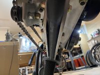
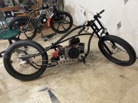
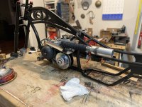
So I started out with a Micargi frame and a predator 212 hemi. I was going to install the motor vertically but I wanted the electric start and that somewhat prohibited me from doing so. I installed the wide crank set up from Affordable Go Karts. I just had to mill out the lower bracket for the sealed bearings. It worked out rather nicely. The lower tube on the Micargi frame is 1 3/8” inch. I cut the kickstand plate and the washer at the back end of the lower tube out and stuffed a 1 1/4” x 1/8” wall DOM tube inside the lower tube about 16 inches long to add some structural integrity to the frame. Initially it was clear that the DOM tubing wasn’t going to slide right in so I threw it in the freezer overnight…
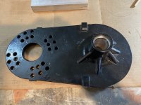
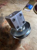
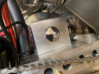
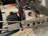
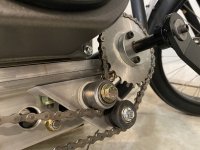
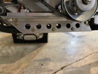
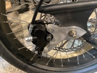
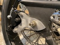
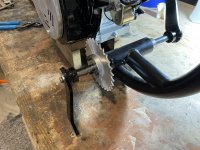
it fit perfectly and all was right in Lugnut’s world. My friend’s son welded two 1/8” plates right below the seat and two 1/8” plates at the tail end of the lower tube right in front of the rear wheel for more structural support. I ordered some 2” x 3” x 3/8“ 6061 aluminum angle and fabricated the lower rails for the motor mount. For aesthetics and a little weight savings I milled 1 inch holes along the aluminum rails with a step bit then bolted them to the lower frame tube using five 3/8” grade 8 bolts and nylon locknuts. I wanted to use a torque converter instead of a centrifugal clutch but using the whole assembly shifted the motor too far to the right to afford any sort of balance. I ended up making a pillow block out of 3” x 3” 6061 aluminum 3 1/2 inches long to house the bearings and jack shaft that carry the driven pulley and rear wheel drive sprocket. This enabled me to eliminate the plate that came with the torque converter, thereby shifting the motor to the left about an inch. It ended up exactly where it needed to be and all was right in Lugnut’s world. I used a 1/2” 6061 aluminum plate 5 3/8 inches wide by about 14 inches long to mount the motor and pillow block to. The belt drive required a specific distance between the crankshaft and the jack shaft. By using the documentation that came with the motor and a little trigonometry I was able to calculate the horizontal distance from the rear motor mount bolts to the center of the pillow block. It’s not adjustable; I didn’t see the need as there are four 3/8” grade 8 bolts with nylon lock nuts holding the motor to the plate and the same holding the pillow block to the plate creating an assembly that does not flex or slip. It worked out perfectly and again, all was right in Lugnut’s world. I milled pockets in the aluminum rails that I bolted to the frame to accommodate the nuts protruding through the half inch plate for the motor and pillow block. The whole assembly was then bolted to the aluminum rails using… you guessed it …four 3/8” grade 8 bolts. More to come…..
Thank you all for reading and allowing me to be here!
So I started out with a Micargi frame and a predator 212 hemi. I was going to install the motor vertically but I wanted the electric start and that somewhat prohibited me from doing so. I installed the wide crank set up from Affordable Go Karts. I just had to mill out the lower bracket for the sealed bearings. It worked out rather nicely. The lower tube on the Micargi frame is 1 3/8” inch. I cut the kickstand plate and the washer at the back end of the lower tube out and stuffed a 1 1/4” x 1/8” wall DOM tube inside the lower tube about 16 inches long to add some structural integrity to the frame. Initially it was clear that the DOM tubing wasn’t going to slide right in so I threw it in the freezer overnight…
it fit perfectly and all was right in Lugnut’s world. My friend’s son welded two 1/8” plates right below the seat and two 1/8” plates at the tail end of the lower tube right in front of the rear wheel for more structural support. I ordered some 2” x 3” x 3/8“ 6061 aluminum angle and fabricated the lower rails for the motor mount. For aesthetics and a little weight savings I milled 1 inch holes along the aluminum rails with a step bit then bolted them to the lower frame tube using five 3/8” grade 8 bolts and nylon locknuts. I wanted to use a torque converter instead of a centrifugal clutch but using the whole assembly shifted the motor too far to the right to afford any sort of balance. I ended up making a pillow block out of 3” x 3” 6061 aluminum 3 1/2 inches long to house the bearings and jack shaft that carry the driven pulley and rear wheel drive sprocket. This enabled me to eliminate the plate that came with the torque converter, thereby shifting the motor to the left about an inch. It ended up exactly where it needed to be and all was right in Lugnut’s world. I used a 1/2” 6061 aluminum plate 5 3/8 inches wide by about 14 inches long to mount the motor and pillow block to. The belt drive required a specific distance between the crankshaft and the jack shaft. By using the documentation that came with the motor and a little trigonometry I was able to calculate the horizontal distance from the rear motor mount bolts to the center of the pillow block. It’s not adjustable; I didn’t see the need as there are four 3/8” grade 8 bolts with nylon lock nuts holding the motor to the plate and the same holding the pillow block to the plate creating an assembly that does not flex or slip. It worked out perfectly and again, all was right in Lugnut’s world. I milled pockets in the aluminum rails that I bolted to the frame to accommodate the nuts protruding through the half inch plate for the motor and pillow block. The whole assembly was then bolted to the aluminum rails using… you guessed it …four 3/8” grade 8 bolts. More to come…..
Attachments
-
 F0B0C02A-C701-4D1C-BEA7-20E0E01D740B.jpeg4 MB · Views: 5
 -
 CA88736C-A990-4022-8F83-F45FC9A815ED.jpeg3.5 MB · Views: 5
 -
 0108E11E-548B-459C-8688-3416A92B4DBF.jpeg3.1 MB · Views: 5
 -
 EB6B05B2-69CF-4D17-8C4F-39C9086FF396.jpeg3.7 MB · Views: 4
 -
 AACC7412-F752-4D61-8209-145D67A3B7E1.jpeg3.4 MB · Views: 2
 -
 82F6B6E2-1056-40FE-9B78-BEB8F2A6B101.jpeg3.1 MB · Views: 5
Last edited:
 it's a bicycle on one side and a motorcycle on the other? How about using the 5 W's
 ")