l008com
Member
- Messages
- 113
- Reaction score
- 21
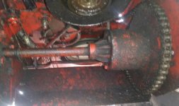
Is this a thing? I have a Manco Dingo so it's a simple solid axle with a giant gear on it.
As we all know, a solid axle with knobby tires will very quickly make a mess of any surface you're driving on. But with an open diff, I might be able to drive across the lawn once in a while without destroying it.
But what about when I'm off road? Well I never am but hypothetically, an open diff with a cable actuated lock machanism would be perfect. When I wanted to have more fun, I could stop, throw the lever and lock the axle. And when I wanted to have less fun, I could stop, throw the lever the other way and unlock the axle.
There are all sorts of mall powered vehicles out there, like ATVs and Gators and stuff. I'm sure many of them do have open or LSD or manual locking diffs. But most of them are also probably drive shaft driven, not chain driven.
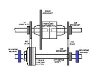
So I'm pretty sure one problem a chain driven open diff would have is that the case/carrier would have to be held still for it to work, which is part of the job the drive shaft does in a car. But my kart has no rear suspension so it wouldn't be much of a problem to attach some kind of stabilizer bar from the case of the differential to the body of the kart.

As we all know, a solid axle with knobby tires will very quickly make a mess of any surface you're driving on. But with an open diff, I might be able to drive across the lawn once in a while without destroying it.
But what about when I'm off road? Well I never am but hypothetically, an open diff with a cable actuated lock machanism would be perfect. When I wanted to have more fun, I could stop, throw the lever and lock the axle. And when I wanted to have less fun, I could stop, throw the lever the other way and unlock the axle.
There are all sorts of mall powered vehicles out there, like ATVs and Gators and stuff. I'm sure many of them do have open or LSD or manual locking diffs. But most of them are also probably drive shaft driven, not chain driven.
So I'm pretty sure one problem a chain driven open diff would have is that the case/carrier would have to be held still for it to work, which is part of the job the drive shaft does in a car. But my kart has no rear suspension so it wouldn't be much of a problem to attach some kind of stabilizer bar from the case of the differential to the body of the kart.