2016 - Ouroboros: An inverted trike.

Status
Not open for further replies.

not_a_bot

Tinkerer
Messages
65
Reaction score
0
Location
Guadalajara, Jalisco, Mexico
As some member kindly suggested, I'm making an entry for this year's build off.

TRIGGER WARNING: Long *** rant.

Now, I got into the whole kart fabrication thanks to my current semester's assignment. We were given the task to design and produce a recreative vehicle, and on a pretty uncommon fashion, we'd chose to our heart's content. That is, we weren't given a set location, terrain, specific user, power source, technology, production processes, nothing at all. I've always liked karts, and since the universe was pointing me out towards them (I've found out it's quite a good idea to go with whatever the universe leads me to) that was my suggestion. Now, this is a team kind of project, so, after analyzing every suggestion, and the difficulty of actually implementing them would pose (we had, back in february/march, a little less than 4 months to get the whole thing put together) it was decided we would follow my route. It kinda helped that I've gathered knowledge about mechanisms, systems and the like, knowledge my partners lacked. Plus, we actually tried to follow 2 other ideas (a wind car, those sails are expensive yo, and a pedal powered boat, in a city where the closest water source to test it was 1 hour away).

After some friendly-ish banter and flashy explanations on my part, a go kart would be our bet. We started to sketch ideas on what path to take, looking up at existing products and the whole shebang product development usually involves, and we stumbled upon Spidercarts' Scorpion. My teammates (2 girls) fell in love with it, and I must admit I got very interested in it too.

As found in this link.

I caught up some issues with their design, there was a brief moment were we actually considered ordering their plans, but then again, where would the fun in doing that be? Besides, there is no such thing as the perfect product, cool thing as that means we'll never be out of work. One of the things that stood up at first sight was how their chair support tube looks like it'd smash that gasoline tank if a bump/hole big enough was hit. Not a fun idea, IMO. Plus, it looked too stiff in their video, so a front suspension was added to the list. Then concerns regarding driver's safety came up (everything is too exposed, no protection whatsoever), and after a brain storm, we had a vague idea of the direction we wanted to go.

Key word, vague.
Documentation began, and there was just so much info available (thanks internet!) that I needed to categorized what would work for us and what wouldn't. This website came up, and it caught me with how organized everything was, not to mention your forums.

Thus, I created an account, introduced myself, and opened a thread asking for advice. My main concern was on what kind of suspension was the right one for me. Once again, loads of info jumped at me. I think it took me like 2 weeks on finally deciding on unequal length, non parallel double wishbone (AKA A-arms) set up.

And so 3D modelling was the next step. As of today, the model is yet to be finished, because realistically, I knew the real deal would differ.

Without further ado, (Actually expect a lot of ado) I present the meager (I tend to focus on working rather than taking pics) photographic evidence of the process of creation for the trike called Ouroboros.

Chapter 1: Inspiration and conceptualization


scorpion.jpg

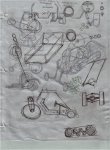
This was the picture that started it all. Both of my teammates were insta-caught by it, and our teacher soon followed. I had my reserves, preferring a 4 wheeled vehicle, but when a teacher gives you a "suggestion", you better listen to it. What follows is a compilation of sketches that are in no way meant as technical drawings, merely landing ideas on paper, first when it was not defined other than a motorized vehicle, then our first sketches at a trike.

Sketches were done with a 4H pencil lead, so I had to bump up contrast.

First attempts at an off-trail requirements list
bocetos 1 (2).jpeg

3 wheeled sketches, I didn't even knew it was a thing.
bocetos 2 (2).jpeg

More doodling
bocetos 3 (2).jpeg

Wouldn't mind pursuing that top view cart
bocetos 4 (2).jpeg

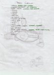
Parts checklist, once we decided on a trike. Plus a faint sketch.
bocetos 5 (2).jpeg

Some early dimensions
bocetos 6 (2).jpeg

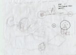
Attempted perspective view based off Spidercarts' stuff.
bocetos 7 (2).jpeg

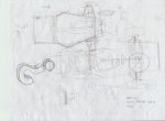
Trying to mechanically decide what to do with steering/suspension
bocetos 8 (2).jpeg

More attempts
bocetos 9 (2).jpeg

TO BE CONTINUED NEXT POST
 

not_a_bot

Tinkerer
Messages
65
Reaction score
0
Location
Guadalajara, Jalisco, Mexico
Chapter 1: Inspiration and Conceptualization Cont.

A-arms make an appearance, as well as rod ends. Side sketch, possible spindle.
bocetos 10 (2).jpeg

What my A-arms could have been.
bocetos 11 (2).jpeg

Spindle thingy, when I planned on a MacPherson strut set up.
bocetos 12 (2).jpeg

When I got learned about suspension geometry, and I was trying to make sense of it
bocetos 13 (2).jpeg


And that's it for today. It's 00:20 and I have less than 5 hours of sleep so I can go to uni and work further on my kart. Will post about all of that eventually. I guess until then I'll get Mod approval for the contest. Nighty yall.
 

landuse

Moderator
Staff member
Messages
18,626
Reaction score
220
Location
Pietermaritzburg, South Africa
Nice. If you want to be entered though, you need to have a picture with a sign stating the password for this years competition. Have a look at the build off rules, they will give you all the information
 

not_a_bot

Tinkerer
Messages
65
Reaction score
0
Location
Guadalajara, Jalisco, Mexico
Nice. If you want to be entered though, you need to have a picture with a sign stating the password for this years competition. Have a look at the build off rules, they will give you all the information

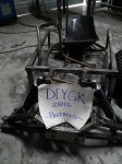
Well I'm dumb. Forgot about the password thingy. See this post's attachments. Much appreciated.


http://www.diygokarts.com/vb/showthread.php?t=32721

Thanks, and as you noticed we have fun here! So you may never live down that "Independent Woman" who can weld not needing a fourth wheel Comment.:thumbsup:

Yes I had to mention that again.:lolgoku:

:roflol: , friendly banter is best banter. Yall folks seem fine to me, I do hope to become a useful member here. And thank you for the link.

SO, as some of you might or might not know, this project has been going on for a bit now, before I read about the build off competition, so I didn't have a chance to take early, passworded pics, but here they are. After this, I'll go back to our beginning.


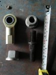
Some spare parts that I haven't moved from home, yet.
evidencia 1.jpg

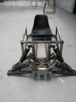
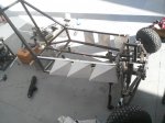
Frame, wheels, seat. In other news, waters wet.
evidencia 2.jpg

Another view.
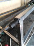
evidencia 3.jpg

Hope this gets me accepted into the sacred area of this year's Build Off.
 

not_a_bot

Tinkerer
Messages
65
Reaction score
0
Location
Guadalajara, Jalisco, Mexico
Yayifictions, approved. Now, back2start.
As a warning, I hadn't weld or about 2 years, when I made a steel bench for another class.
Then nada (woodworking for some furniture, then designing a toilet, then shoes and accessories), when suddenly, metal work mad skills were needed.
So yeah, expect some really messy welds, welding with a buzz box and 6013 electrodes is not as fun at the beginning. And the re-learning curve was steeper for my teammates. I couldn't really deny them working, plus I needed the extra hands. More onto that later.

Chapter 2: Modeling

Using SolidWorks, I started the 3D modeling, for I'd needed to visualize what went there, and dimensions and stuff. Ignore the date on my clock, I'm digging up my old files.

First version: Overlapped tubes, going for a one A-Arm, no ball/heim joints.
primer modelo.jpg

Added tires and another arm, going for a parallel, equal length set up.
primer version vista iso.jpg

Couple views of the suspension set up.
brazos frontales primer version.jpg

primer version brazos iso.jpg

Second version: Here I was toying with the oh so very good looking cantilever suspension set up, turns out I learned a bit later that it is indeed very good, but for track use, not so much for off-trail, as it shortens the shock's travel, because levers.

suspension cantilever.jpg

Third and final-ish version: Once I got learned on suspension geometry, we decided to go for a double wishbone set up. Here's a screenie of where it all began.

modelo base sola.jpg

Thing we are currently pursuing, with modifications made on the fly, as needed. Unequal length, non parallel arms.

modelo iso.jpg

vista frontal.jpg

vista lateral.jpg

TBC
 

not_a_bot

Tinkerer
Messages
65
Reaction score
0
Location
Guadalajara, Jalisco, Mexico
Chapter 3: Parts list, part uno.

Be it noticed, parts and stuff have been being bought through the entire process, from different sources, and second hand when possible, to reduce costs. I'm simply collecting it all in one (or maybe two) posts for convenance sake. Once again, since I was ignorant of the 2016 Build Off competition, no passworded sign will be present.

Here's the muscle of our build. An GX200 clone, made by Oakland (a subdivision of High Power Tools, a mexican tool and machinery company that outsources production to, you guessed it, China), boasting of producing 6.5 HP @ 3600 RPM. The usual thing most of you will be familiar with.
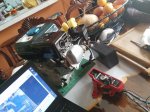
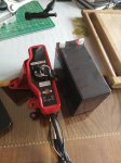
I got it with an electric starter, the key switch control box, a battery and no instructions on the electric starter installation whatsoever. The engine instruction manual was so badly printed, and the "illustrations" of such a bad quality, they were useless. Here it sits on my dinning table.

motor desempacado.jpg

arranque electrico y bateria.jpg

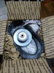
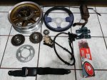
As per suggestions on another forum (and research to validate their claims) I ordered a torque converter from eBay, as found on this link.
It came nicely packaged, and with a fast (for our standards anyway) shipping.

CVT empaque.jpg
CVT empaque 2.jpg

CVT empaque 3.jpg

Here they meet for the first time!

motor + cvt desempacado.jpg

At this point, I had yet to make the engine run for its first time, because I had no idea how to wire the control box, and tutorial weren't helping, as I had an extra cable and my cable colors didn't match anything everybody else had. after a look at the original GX200 manual, I was able to be check my circuitry and make an educated guesstimate of were to connect what. Turns out I made it.
Here's video link of the thing running.

By the way, the engine came with the throttle lever fixed on the almost fully opened position, and no return springs at all. thankfully google and youtube provided enough info on what to do, and got it running nice and smooth.

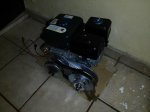
Then, it was time to get my CVT installed. After the usual engine oil cap grinding (no pics of it, sorry) it fit right in. The provided bolt meant for fixing the driving pulley to the engine's shaft was of the wrong size/thread, a quick trip to my local bolt store fixed that.

motor + CVT.jpg

I still have some 3 attachments slots, so we move on to wheels.
145-70R6, used. Have enough life to help me measure and fit, and maybe test the thing, but I will replace the rubbers. One had its bearings seized, just yesterday I bought the replacements, for both of em. They will make up the front wheels.

llanta.jpg

I got real lucky on this one. Hunting for sprockets and the like on some industrial junkyards, I saw shiny, and shiny is pretty, specially when surrounded by old, beaten and dirty machinery guts. Turns out they were 6 heim joints, female, left hand threaded. Asked the guy for their price, he seemed to ponder on it, guesstimated, and I bought all 6 of them. I paid for all less than I would have for just one of them, if bought new. Later, measuring them at home, I had three 3/4" joints, and three 5/8" joints working perfectly.

rotulas.jpg


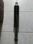
And here are the motorcycle shocks that will make our ride smoother. Found on work bikes such as the (at least locally called) Honda Cargo 150, they measure 33 cm from eye to eye. I used this measure for the model on the previous post, btw. One pair for the front suspension, one pair for the rear one.

amortiguador.jpg

TBC
 

not_a_bot

Tinkerer
Messages
65
Reaction score
0
Location
Guadalajara, Jalisco, Mexico
Chapter 3: Parts list, part dos.

#40 chain. Gotta get me a second master link btw.

cadena.jpg

Pillow block bearings, for a 1" shaft that I have no picture of, but there it is. Have 4 total, because I need to run a jackshaft, and the shaft is long enough that I can cut it in half and get the 2 I need.

chumaceras.jpg

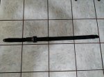
Seatbelt because safety.

cinturon.jpg

Small muffler. It sounds noticeable nicer than stock box, but it need some prettifying, plus the tube will be modded to fit my application.

escape.jpg

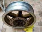
Rear wheel rim. 12x3.5, still has no tire, but I know where to pick it up. Haven't gotten around to it, most likely tomorrow.

rin delantero 2.jpg

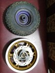
Here it is compared to the front wheels.

compara.jpg

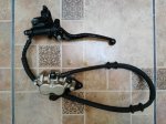
Got a bike disk brake system, minus the disc, which comes affixed to the rim previously posted. It's already working, plug and play.

freno.jpg

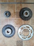
Sprockets, all of them in #40. Small one is 16T, then two 30T (originally I thought this would be it, but Sid's calculator showed I needed a bigger number of teeth, at least on one sprocket, which lead us to:) and a 40T sprocket. Ratio is 8:1, adding the CVT I have a lowest ratio of 21.6:1 and a highest ratio of 7.2:1. Sounds about right, right?

sprockets.jpg

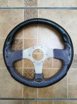
Steering wheel, light but sturdy, feel really nice.

volante.jpg

The whole gang, plus the brake cable. I intend to drill a small hole for said cable in the brake's handle, and use it as a lever that way, the cable connecting it to my brake pedal. Hope that makes sense for yall.

grupo con chicote.jpg

TBC
 

chancer

ɔ ɥ ɐ u ɔ ǝ ɹ
Messages
9,358
Reaction score
8
Location
COMFORT, TEXAS
Cool parts. Cool name.
The Ouroboros is an ancient symbol depicting a serpent or dragon eating its own tail. The name originates from within Greek language; (oura) meaning "tail" and (boros) meaning "eating", thus "he who eats the tail".
 

not_a_bot

Tinkerer
Messages
65
Reaction score
0
Location
Guadalajara, Jalisco, Mexico
Chapter 4: Fabrication.

Here we go. Square 1" profile, first order (2 x 20ft) were 12 gauge, then we moved to 14 gauge.

First pieces of tubing cut. Oh boy, was I stoked at how fast it went.
If only I knew.
1 corte piezas .jpg

Thing welded as per the model. Mostly improvising with little thought to future parts.
2 base.jpg

Added side tubes, we kite now.
3 marco base.jpg

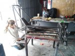
Started to attach what would make the 2nd level, plus 7 out of 8 45° supports for the upper A-Arms. We had the hardest time welding those, so that the missing piece had a huge hole and it was no longer usable. Turns out, it was the freakin' magnet we held the pieces with. Took us an embarrassingly long time to figure it out, and many utterly ugly welds too.
4 marco 2do piso .jpg

Another shot of the front part.
5 bases brazos.jpg

Some more. Plus black fingernails.
6 marco wip.jpg

Here's how it looked like by the end of that day. Spirits still high.
7 marco wip 2.jpg

More tubes added! Plus the missing support. This was the day we learned to respect magnets. How do they even work?
7.5 marco wip.jpg

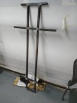
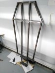
Upper frame progress. By now people keep asking us why were we making a metal coffin.
8 marco 2do piso.jpg

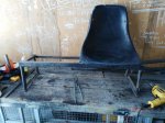
Here's the seat we plan to use, as we got it.
9 asiento.jpg

TBC
 

not_a_bot

Tinkerer
Messages
65
Reaction score
0
Location
Guadalajara, Jalisco, Mexico
Chapter 4: Fabrication Cont.

I guess I should say that these photos are a very shortened version of the process. And that I forgot to take pictures a lot. Also, by the point were we got the seat, I had wasted a lot of time trying to fix messy welds done by all 3 of us. Lacking proper technique, this was a long tortuous task. Learned too late to focus on functionality, and prettify stuff later. It is worth mentioning that this was all done on my University's workshop, were we have not nearly enough tools, machines and equipment, and sometimes we lost time waiting for a certain machine or tool to be free/available at the warehouse. Specially since, for one class, every student must learn how to weld pretty beads on a 30 cm x 30 cm piece of metal. Yup, that buzz box sure sees busy days. Couple of days were lost to a power outage too, lol. So yeah, loads of factors that affected our work. Yeah, I seem to have a lot of excuses, but let's move on.

Seat was not attached, as you can see frame is not closed, added to the to-do list.
10 asiento marco.jpg

Tet fitting upper arms.
11 brazos prueba.jpg

And lower arms.
12 brazos inf prueba.jpg

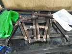
Arms we made some day I forgot to document.
13 brazos juntos.jpg

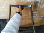
Piece of metal bend to follow the seat curve, intended to complete the frame, and give more stability to the whole seat.
14 solera respaldo.jpg

Lower frame cut to the desired width.
15 asiento recortado.jpg

Frame only. Seat used to be riveted to frame.
16 asiento recortado frame.jpg

Just messing around seeing how it'd look. Of course, its too high as of yet.
17 asiento prueba.jpg

Picture of thing.
18 asiento prueba 2.jpg

More pieces. We drew the A-arm measures on a piece of wood I knew was straight, drilled some holes and tied it all down in position. Was not as accurate as I'd like as we learned later, but it was good enough.

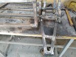
Here we have a picture of my misaligned as heck holes. Drilled em with a hand drill, 1/2" because that's a nice, symmetric measure. PITA to be honest. I learned then pre-drilling with the column drill and then welding would be was easier. That, and that we could have devised a better way of cutting/holding the support pieces, as their misalignment became patent right then.
19 brazos y base.jpg

TBC
 

not_a_bot

Tinkerer
Messages
65
Reaction score
0
Location
Guadalajara, Jalisco, Mexico
Chapter 4: Fabrication Cont.

We still on how misaligned these holes are.
21 perfo base mas chueca.jpg

That electrode had almost no wiggle space.
22 eso no es una recta.jpg

Will look nice once polished.
23 acero pulido.jpg

Couple more views of the base.
24 base wip.jpg

25 base wip 2.jpg

After bashing and grinding and bending made those fit so that they would move smoothly on the arc they were supposed to.
26 tornillos i.jpg

Same here. A round file made the fitment a lot easier. Mangled perforations tho. Holes on arms were done with hand drill too. PITA.
27 tornillos d.jpg

A probable position for that joint nut.
28 posible posicion.jpg

5/8" joint and crew.
29 5 ocho.jpg

3/4" joint and crew.
30 3 cuatro.jpg

TBC
 

not_a_bot

Tinkerer
Messages
65
Reaction score
0
Location
Guadalajara, Jalisco, Mexico
Chapter 4: Fabrication Cont.

Figured I should mention, those heim joints I found were left hand threaded, and the guy at the bolt n nuts shop told me I would have to get them specially made. While I was pondering on the economical implications, he suddenly had an idea that saved me time and money.
Using tire lug bolts (I was lucky enough that the 2 measures I had, 3/4" and 5/8" were common so that he still had some laying around, and that the thread count was the same).

In fact, the bigger one fit with little wiggle room in my square tubing. We ended up doing something different, but it could have been helpful.

Also, we are closing all the open ends using 1/2" x 1/8" steel squares.

3/4" lug bolt fits there nicely.
31 funda.jpg

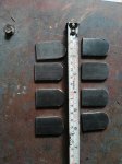
From the same material used to close open ends, we cut tabs for the shock bolts.
32 tapas aortiguadores.jpg

All welded, fit test. Also jumped on it because yeah.
33 prueba a.jpg

Another angle, people now kinda realize its not a coffin.
34 prueba a.jpg

Brackets that will be our pivot point between engine frame and driver's frame. Same 1/8" material.
35 brackets.jpg

Added an inner piece of tube for support.
36 bracket termiando.jpg

Some bearings on our wheels were seized, took em apart, cleaned everything, replaced bearings.
37 llantas baleros.jpg

NOT PICTURED: A ton of work to make the heim joints parallel to the ground when the shock was at its resting position (not under tension or compression), figured this way we'd have most of the travel or heim joints could provide. Using some pipe that barely fit around our lug bolts, and some pieces of metal to get the desired angle, we welded everything together. Not pretty, but it works. I tend to overstructure this thing as you might have noticed thought the whole build, but I'd rather do this than have something break when driving it.

Here's how the joints would be, once the spindles are in place. Notice the upper joint has a lot of adjustment, so tat I can control my angles.
38 separacion rotulas.jpg

Top view. Notice the difference on the vertical plane. This is to have a bit of positive caster. Front of cart to the left.
39 rotulas superior.jpg

Tabs attached, back now more complete. That was it for that day.
40 estructura en pared.jpg

TBC
 

not_a_bot

Tinkerer
Messages
65
Reaction score
0
Location
Guadalajara, Jalisco, Mexico
Chapter 4: Fabrication Cont.

Oh yeah, forgot to mention, we are using grade 5, 1/2" bolts with nylon insert lock nuts on all A-Arms and pivoting brackets.

I'm missing pictures, but we are getting closer to where we currently are.

We got the sheet that will protect the driver from rocks and stuff, separate their feet from the front suspension and other bits.
40algo lamina.jpg

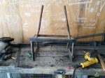
Here's the whole front part done. Sent the seat to get some upholstery and that's it.
41 estructura frente.jpg

Another view.
42 estructura lado.jpg
Since I needed to make up for the slight, kinda intended difference between joints, that makes up the kingpin inclination angle, I kept it simple and devised this as spindle:
43 masa prefab.jpg
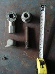
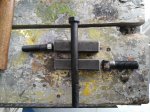
Leftmost bolt is 5/8" (upper joint), rightmost is 3/4" (lower joint), long bolt is 5/8" x 7", where our front wheel will sit tight. All bolts grade 5, same nylon insert nuts.

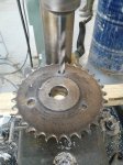
Had to make some new holes, a teacher that happened to be around helped me loads in figuring out how to get my rear wheel fixed to the axle, will have the thing ready later today, more pictures then. I'm pretty much using the sprocket in this picture as a spacer.
44 barrenacion catarina.jpg

Forgot to take pics of the spindle all welded up. In order to limit the wheel travel once bolted in (the threaded part of the long 5/8" bolt didn't reach to the other side of the wheel hub), a pipe that sat tight on the bolt, with a diameter just large enough to sit against the inner side bearing provided the support we needed.
45 llantas instaladas.jpeg
Here positive caster makes itself known. Once we leveled the rear part to the estimated riding height, we tested the suspension, there's little to no risk of the lower A-arm hiting the ground, but, worst case scenario, we flip both arms, weld new shock mounting tabs on what used to be the bottom side, and voila. Or something.

Another pic of it. Pipe on the left is just laying there, to attached to anything.
46 llantas.jpeg

Bonus pic of the gal that has taken over welding, she's developed nice skills through this project.
bonus weld.jpg


And so far here we are, pics on this post were taken yesterday, minus the gal one. Once I figure out the rear wheel sprocket + brake disc + brake assembly thingy, we'll do the engine side of the frame (our jackshaft will be elevated a bit to reduce horizontal length) and hopefully we'll piece everything together in one day. Tomorrow school´s closed, so we have Tuesday to get this thing rolling, as on Wednesday we re supposed to have it, at least functionally speaking, finished. It will be a long day.

I'll go junkyard hunting tomorrow for a rack and pinion, buy the missing pair of shocks for the engine mount, figure how to build out own set of pedals, and try and have everything ready so that there are no interruption on Tuesday. And find some time to finish the 3D modeling, documentation, technical reports and all that boring stuff.

And I must not forget about my other subjects. Oh well it will be worth it.

Now yall can give me a proper bashing and tell me why and how we are going to fail.

TBC
 

not_a_bot

Tinkerer
Messages
65
Reaction score
0
Location
Guadalajara, Jalisco, Mexico
Update, kind of. Good news! My team's due date was moved from tomorrow to this Monday. Great, as we have a ton of work left. So, once again, I missed a ton of pictures.
I got my hands on an hydraulic rack and pinion, Chrysler if the label on it is to be believed.
It included everything up to ball joints, so I thought that would work wonders. Turns out it was way bigger than we needed, so in true DIY fashion, we shortened the thing, while leaving it totally functional. I love how versatile an angle grinder can be.
Unplugged the lines, and everything worked just as good, as I was told it would. Installed it into the cart, now we just need to get the rear wheel axle done to get me some Ackerman angle up in this.
One of my teammate began cutting a thin sheet of styrene to begin modeling what will later become the cart's fiberglass body.
Also, got the engine's cradle done, but since I forgot to get nuts and bolts fo the engine and pillow block bearings, we stopped here. By the way, what size/length should I use for securing my engine?

Have what little photos I took.


Picture (not mine) of how my rack n pinion looked. Only, of course, more beaten up and dirtier.
dir27.jpg

Body model. We're going for an aggressive look.
47 carcasa inicio.jpg

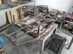
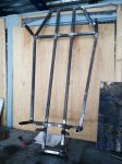
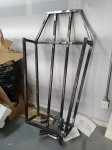
Engine will sit on that cage thing. Shocks will go from that backrest tubes, to a point on the engine cage yet to be decided. Tabs that will be used as mounting pivots for the shocks are already cut and drilled to size. You can see a bit of a steering arm just laying there, by the tire. Pillow blocks for the jackshaft will be bolted upside down right at the back end of the cage's upper tubes. That thick piece of black tube to my water bottle's left is what we cut form the rack and pinion. Also, partner welded the hinges on opposite sides to what they should be, so we have to sort out some misalignment there. Most likely re-drill em. I'm still thinking the engine's cage is too close to the front of the car, but whatevs.
48 jaula motor.jpg

Bonus pic of our clutter, other student's projects as background. You might notice my rear wheel has the sprocket and disc brake installed so that they won't mess with each other.
bonus clutter.jpg

Tired af, had a long long day. Until next report (tomorrow because yeah).

TBC
 

Poboy kartman

Senior Moments Member
Messages
12,461
Reaction score
1
Location
White Settlement Texas
Hey vato!!! Arriva arriva!!!!! Andeleh andeleh....(Sorry I speak poquito Spanish....) and can't spell any of it....:lolgoku:

I know...I know.....Catta la seko....(can't spell that either! )...:surrender:
 
Status
Not open for further replies.
Top